


6
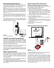
The REMM also has five independently programmable re-
lays. The relay programming options are explained in the
programming summary, Block 7.
The AUX terminal on the S5050 REMM is capable of supply-
ing up to 100 mA of output current to power sensors and
other devices.
NOTE: Total combined current from the relays and AUX
output terminal may not exceed 100 mA.
Refer to the S5050 REMM Installation Instructions (P/
N 5-051-453-00) for additional information regarding the
set up, configuration, and operation of the S5050 REMM.
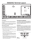
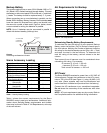
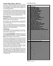
Figure 8
The S5050 Relay/Event Memory Module (REMM) PCB Layout
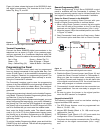
S5058 Zone Expansion Module
The Sierra S5832SG control panel has eight hardwired
zones and may be expanded up to 32 zones. Eight addi-
tional hardwire zones are obtained by connecting an
S5058 Zone Expansion Module to the keypad data bus.
Up to three S5058 ZEMs may be connected, providing a
total of 24 additional zones.
NOTE: Trouble conditions and tampers, if enabled, are re-
ported via the keypad bus. The report routing is defined in
Block 4, CL 158 and 159, respectively.
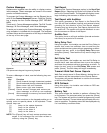
Power is supplied by connecting the KPWR terminal on
the S5058 ZEM PCB to the KPWR or AUX terminal on the
control panel and the C terminal on the ZEM to the C ter-
minal on the control panel. The GND terminal on the ZEM
PCB is for connecting earth ground to the ZEM.
There are two VOUT terminals (connected in parallel),
which can provide up to 300 mA of output current to power
sensors or other devices.
Each S5058 ZEM will support up to 8 hardwired zones. If
a zone is programmed as a SpreadNet zone (see Block
2, CL 111 - 142), it is not available for use as a hardwired
zone.
Additional setup and wiring information is available in the
S5058 Zone Expansion Module Installation Instruc-
tions (P/N 5-051-454-00).
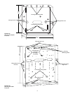
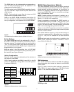
Figure 10
S5058 Zone Expansion Module (ZEM) PCB Layout
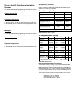
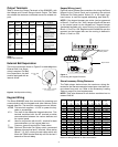
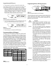
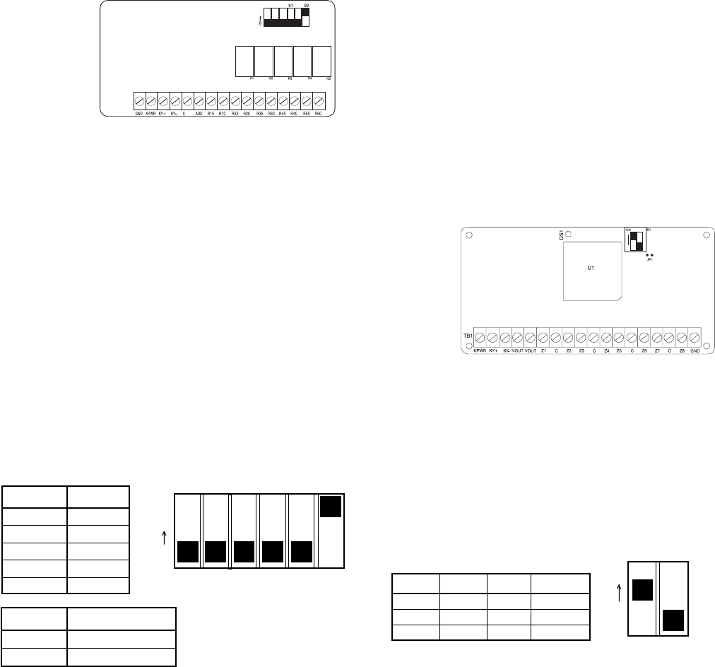
Addr. S1-1 S1-2 Zones
1 on off 9 - 16
2 off on 17 - 24
3 on on 25 - 32
S1-1 S1-2
ON
Figure 11
Addressing the ZEM
ZEM Addressing
S1-1 and S1-2 are used to address the ZEMs. The ZEM ad-
dress determines which zones are added to the S5832SG
control panel.
Figure 11, below, shows the switch settings to address the
ZEMs. ZEM #1 is used to add zones 9 - 16; ZEM #2 adds
zones 17 - 24; and ZEM #3 adds zones 25 - 32.
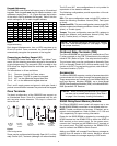
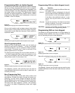
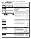
Switch Relay
S1-1 R1S
S1-2 R2S
S1-3 R3S
S1-4 R4S
S2-1 R5S
S1-1 S1-2 S1-3 S1-4 S2-1 S2-2
ON
Figure 9
REMM Switch Settings (shown in default position)
Switch REMM
S2-2 ON = REMM #1
S2-2 OFF = REMM #2
Switch Settings
The S5050 REMM has five (5) dip switches (S1-1 thru S1-
4 and S2-1) which can be used to provide AUX power to
the relay outputs. The default setting for each switch is
OFF. In this position, each relay uses the switched (S)
and common (C) terminals. Each relay is independently
programmable by the installer.
With the switch in the ON position, the +12 VDC AUX
power is applied to the respective Relay switched (S) out-
put terminal (see Figure 9, below).
Switch Configuration
Figure 9, below, shows the relationship of the switches to
the relays on the REMM.
S2-2 is used to address the REMM. Leave S2-2 in the ON
position for REMM #1. Change S2-2 to the OFF position
to address REMM #2.