


7
Digital Communicator Connections
Removing/Installing the Digital Communicator
The digital communicator plugs into the control panel PCB
and is secured by a nylon retaining screw.
To remove the digital communicator:
1) Remove AC and DC power from the control panel.
2) Locate and remove the nylon screw. The screw is located
near the upper right-hand corner of the digital commu-
nicator PCB. (See page 1, Figure 1.) Use a #1 phillips
head screwdriver to remove the retaining screw.
3) Unplug the digital communicator from the control panel.
To install the digital communicator:
1) Ensure that AC and DC power have been removed from
the control panel.
2) Carefully plug the digital communicator into the control
panel PCB. Misalignment of the pins could damage the
control panel.
3) Replace the nylon retaining screw.
4) Apply power.
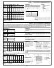
Line #1
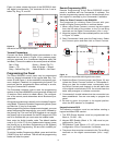
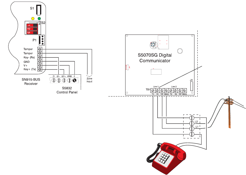
Figure 13
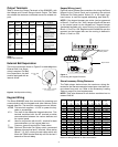
Telephone Connections
Digital Communicator Telephone Connections
The Sierra S5832SG control panel can support either a one-
or two-line plug-on digital communicator.
The digital communicators have four terminals for connec-
tion to the telephone lines. These terminals are labelled:
Tip, Ring, T1, and R1. The single-line digital communicator
has one set of terminals and the dual-line digital communi-
cator has two sets of terminals. Figure 13 shows how to con-
nect the digital communicator to the incoming phone lines
and the house phones using either a single-line or a dual-
line digital communicator.
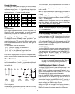
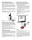
SN915-BUS SpreadNet Receiver
The SpreadNet SN915-BUS Bus Receiver connects to the
keypad bus and provides the communication link for all
SpreadNet keypads/keyfobs and zone transmitters.
NOTE: Tamper and trouble conditions, if enabled, are re-
ported via the keypad bus. The report routing is specified in
Block 4, CL 158 and 159, respectively. Low Battery Report
Routing for the SpreadNet Transmitters is programmed in
Block 4, CL 157.
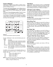
Power for the SN915-BUS may be supplied from either the
KPWR or AUX and C terminals on the control panel to the V+
and GND terminals on the SpreadNet Receiver (see Figure
12).
For additional information on wiring and configuration of the
SN915-BUS Receiver, refer to the SN915-BUS Installation
Instructions (P/N 5-051-440-00).
Figure 12
Connecting the SN915-BUS
SN990/991 SpreadNet Keypad/Remote
The control panel can support up to eight SpreadNet key-
pads. There are two different models available, the SN990-
KEYPAD and SN991-REMOTE. Both devices are battery
operated and communicate with the panel through the
SpreadNet SN915-BUS RF Receiver.
SpreadNet keypads provide one-way communication only
and do not display any panel status information.
Additional information on the SpreadNet keypad and remote
may be found in the SN990/991 Installation Instructions (P/N
5-051-556-00).
SN961 SpreadNet Keyfob
The control panel can have up to eight SpreadNet keyfobs.
Each keyfob will be associated with a specific user number
and will arm, home arm, or disarm the system just like the
user code. The keyfob will communicate with the control panel
via the keypad bus.
SpreadNet keyfob allows one-way communication only and
cannot display any panel status information.
For information on programming the SpreadNet keyfob, refer
to the SN900-PROG Operating Manual (P/N 5-051-136-00
Rev C or later).