


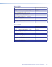

MLC 64 RS VC D Specifications
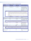
Control — host ports
Serial control port ........................... 1 bidirectional RS-232 on a 3.5 mm captive screw connector, 3 pole
Baud rate and protocol ................... 9600 baud, 8 data bits, 1 stop bit, no parity
Serial control pin configuration ....... Pin 1 = Tx, pin 2 = Rx, pin 3 = GND
USB control port ............................. 1 front panel female mini USB B
USB standards ................................ USB 2.0, low speed
IR learning frequencies ................... 30 kHz to 60 kHz
IR learning distance ........................ 4" (10 cm) to 14" (36 cm) from the receiver
Program control ............................. Extron conguration program for Windows
®
Extron Simple Instruction Set (SIS
™
)
Control — serial port
Display control port ........................ (1) 3.5 mm captive screw connector, 2 pole for unidirectional RS-232 control
(±5 V)
Baud rate and protocol (RS-232) ..... 9600 (default), 19200, 38400, 57600, 115,200 baud; 8 (default) or 7 data bits;
1 stop bit; no parity (default), or even or odd parity
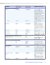
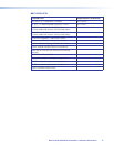
Control — IR/serial port
IR control port ................................ (1) 3.5 mm captive screw connector, 2 pole for IR/Serial* (transmit only)
TTL level (0 to 5 V) modulated infrared control from 30 kHz up to 60 kHz, or
±5 V RS-232 control (transmit only)
*IR/serial ports are congurable via software; serial communication is the
default.
Baud rate and protocol ................... 9600 (default), 19200, 38400, 57600, 115,200 baud; 8 (default) or 7 data bits;
1 stop bit; no parity (default), or even or odd parity
Control — relay
Number/type .................................. 2 momentary or latching (configurable via software)
Connector ...................................... (1) 3.5 mm captive screw connector, 3 pole
Contact rating ................................ 24 V, 1 A
Control — digital input monitoring port
Number/type .................................. 1 digital input (configurable)
Connector ...................................... (1) 3.5 mm captive screw connector, 2 pole
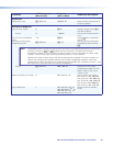
Digital inputs
Input voltage range ................. 0-24 VDC
Input impedance ...................... 12k ohms
Programmable pullup ............... 2k ohms to +5 VDC
Threshold low to high .............. >1.5 VDC
Threshold high to low .............. <1.0 VDC
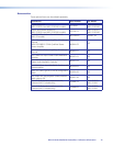
Control — peripheral audio equipment
Volume control ............................... 0 to 10 VDC variable voltage, positive logic (the higher the voltage, the higher
the volume)
Mute control .................................. Momentary push switch with latching contact closure during mute; LED mute
indication
Pin configuration ............................ Pin 1 = +10 VDC, pin 2 = volume/mute (variable voltage), pin 3 = GND
Reference voltage ........................... 10 VDC
MLC 60 Series MediaLink Controllers • Reference Information 66