


Wiring for IR Control
To control devices via infrared (IR) commands from the MLC, connect one or two IR
emitters to the IR/S port (RS models) or the IR port (IR model). The IR and IR/S ports provide
unidirectional IR signal output to control a display, projector, switcher, or other device such
as a VCR or DVD player.
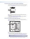
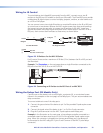
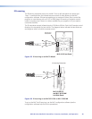
You can connect one or two single IR emitters or one dual IR emitter to the IR or IR/S port
to control one or two devices. Because the MLC captive screw plugs have small openings
that accept just one wire per pole, to connect two IR emitters to the MLC, insert one
ground wire (black) and one IR signal wire (black with a white stripe) in the MLC 62 IR or
IR/S port, then connect the IR emitters to those wires, as shown below.
Two Single IR Emitters
One Dual IR Emitter
(+)
(–)
IR Signal
Ground
(+)
(–)
(+)
(–)
Black Wire with White Stripe
Black Wire
Legend
VCR
DVD Player
(+)
(+)
(–)
(–)
IR Signal
Ground
Figure 23. IR Emitters for the MLC 60 Series
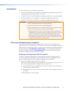
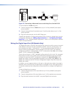
For IR control, there can be a maximum of 50 feet (15 m) between the IR or IR/S port and
the IR emitters.
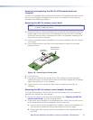
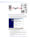
Example: The illustration on the next page shows a single IR emitter connected to the
IR/S port of an MLC 62 RS D or an MLC 64 RS D.
MLC RS D Rear Panel
Rx
Tx
GROUND
Tx/IR
COMMON
1
1
2
HOST/
CONFIG
DIGITAL
INPUT
Tx
PWR
12V
0.4 A MAX
RELAYS
N/O
GROUND
GROUND
GROUND
GROUND
+12 VDC
50'
(15 m)
PORT B
IR/ S
PORT A
RS-232
Ground ( )
IR Signal
IR Emitter
Figure 24. Connecting an IR Emitter to the IR/S Port of an MLC RS D
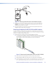
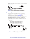
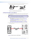
Wiring the Relays Port (RS Models Only)
Connect one or two devices such as room lights, a projector lift, or a motorized screen
(shown in the example on the next page) to the Relays port. This port accommodates two
relay connections.
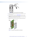
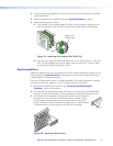
To connect a device to one of the relay ports:
1. Connect the ground wire of the device to pin 3 of the provided 3-pole captive screw
connector.
2. Connect the signal wire of the device to pin 1 or 2 of the 3-pole connector.
3. Plug the 3-pole connector into the MLC 3-pole captive screw Relays port.
Example: In the illustration on the next page, a low-voltage controller connected to a
motorized screen has been wired to pins 2 and 3 of the provided 3-pole captive screw
plug. When this connector is plugged into the rear panel Relays port, the device will
be connected to the MLC relay port 2 (pins 2 and Common of the MLC 3-pole Relays
connector).
MLC 60 Series MediaLink Controllers • Features, Installation, and Operation 23