


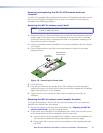
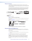
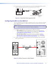
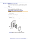
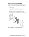

2. Plug the connector into the rear panel Pwr connector. In the example below, a power
supply is being connected to the Pwr connector of an MLC 62 RS D.
External
Power Supply
(12 VDC)
MLC Rear Panel
Rx
Tx
GROUND
Tx/IR
COMMON
1
1
2
HOST/
CONFIG
PORT A
RS-232
IR/ S
DIGITAL
INPUT
Tx
PWR
12V
0.4 A MAX
RELAYS
N/O
GROUND
GROUND
GROUND
GROUND
+12 VDC
Ground
12 VDC Input
Ground All Devices
Figure 30. Connecting a Power Supply to an MLC
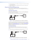
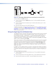
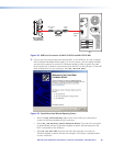
Configuring the MLC via the USB Port
The mini-Type B USB port can be used to configure the MLC via the configuration software
and to update the firmware. This USB port also functions as a power source for the MLC
during configuration.
NOTE: Do not use this port as the permanent power source for the MLC. It should be
used for power only during button and port configuration.
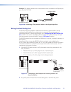
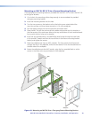
1. If the MLC has already been installed, access the USB port as follows:
• MLC D models: Remove the wallplate from the unit to access the USB port,
which is located on the front panel behind the wallplate (see “Accessing the
Covered MLC D Front Panel Features,” later in this section).
• MLC 62 RS EU and MK: Remove the MLC from the installation surface to
access the USB port, which is located on the left side panel (see “Accessing
MLC 62 RS EU and MK Side and Rear Panel Features,” later in this section).
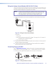
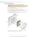
2. Connect a USB A to mini B cable between the USB conguration port and the USB
port on your computer.
USB Cable
Type A
USB
Mini Type B
USB
USB 1
USB
Ports
PC
MLC 62 D Front Panel
VOLUME
DISPLAY
Extron
PC
VIDEO
LAPTOP
MUTE
ON
OFF
Figure 31. USB Port Connection for MLC D Models
MLC 60 Series MediaLink Controllers • Features, Installation, and Operation 27