


Installation
The MLC 60 Series can be installed as listed below:
• The MLC 62 D models can be installed in a standard one-gang electrical wall box or a
one-gang Decora mounting bracket (“mud ring”).
• The MLC 64 RS VC D can be installed a two-gang electrical box or mounting bracket.
• The MLC 62 RS EU can be installed in a standard one-gang EU junction box.
• The MLC 62 RS MK can be installed in a standard one-gang MK junction box.
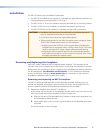
CAUTIONS: • Installation and service must be performed by authorized personnel
only. UL listed electrical boxes are recommended.
• Ensure that the junction box is grounded properly.
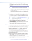
• When stripping wires for use with the captive screw connectors, leave
3/16 (5 mm) of bare wire to insert into the connector.
• Exposing more than 3/16 inch of the copper wires could allow the
stripped wires to touch each other, causing a short circuit. This could
result in the external DC power supply overheating and burning.
• Stripping the wires to expose less than the recommended amount
may cause them to slide out of the connector too easily, even if they
are tightly pinched by the captive screws.
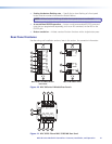
Removing and Replacing the Faceplates
Each MLC model is delivered with a faceplate (bezel) attached. This faceplate can be
removed if you want to replace any of the buttons or exchange the faceplate for another.
Replacement kits containing six-button or eight-button faceplates and additional buttons
can be ordered (see “Part Numbers and Accessories” in the “Reference Information”
section or the Extron website at www.extron.com for information on parts that are
provided or available to order for each MLC model).
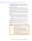
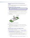
Removing and replacing an MLC D faceplate
The MLC D models are delivered with a black faceplate attached. If desired, you can
remove this faceplate and replace it with the white one that is also provided with the
product. (Matching black and white Decora wallplates are also provided.)
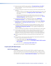
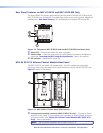
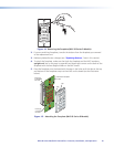
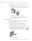
1. Remove the faceplate from the MLC D as follows:
At the center top and bottom of the faceplate are tabs, which insert into slots on the
MLC main board and hold the faceplate in place. For each tab:
a. Insert the at end of the provided Extron Tweeker or other small screwdriver into
the hole above or below the tab.
b. Pressing each tab in and up, pry the top and bottom of the faceplate away from
the board.
See the illustration on the next page.
MLC 60 Series MediaLink Controllers • Features, Installation, and Operation 17