


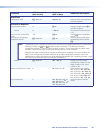

X1@
= Name of the MLC device.
May be up to 24 alphanumeric characters. The first character must be
alphabetic; the last character cannot be a hyphen or minus sign (-). No blank or
space characters are permitted.
X2#
= Status
0 = disengaged (default)
1 = engaged
X2%
= Firmware compatibility version number (a 3-digit number listed to three
decimal places: nnn.nnn)
X2^
= Device configuration compatibility version number (a 3-digit number listed to
three decimal places: nnn.nnn)
X4(
= Default product name: MLC-62-RS, MLC-62-IR, or MLC-64-RS
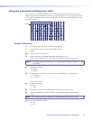
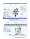
X5)
= LED status
A 32-digit number, each digit of which represents the status of an LED on the
MLC front panel. In
X5)
, the LED statuses are represented in descending order
from 32 to 1; that is, the first digit on the left represents LED 32, the second digit
represents LED 31, and so on. The last digit of the number represents LED 1.
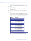
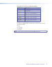
On the MLC 62 models, the LEDs are numbered as follows:
LED Number LED Location
1 Transmit red
2 Transmit green
3, 4, 5, 6 Four LEDs behind “Display” text
7 Button row 1, first LED (button 1)
8 Button row 2, second LED (button 2)
9, 10, 11, 12 Four LEDs behind “Volume” text
13, 14, 15, 16, 17 Volume level indicator LEDs 1 through 5
18 Button row 2, first LED (button 3)
19 Button row 2, second LED (button 4)
20 Button row 3, first LED (button 5)
21
Button row 3, second LED (lights only if
buttons 5 and 6 are combined)
22 Button row 3, third LED (button 6)
23 Button row 4, first LED (button 7)
24
Button row 4, second LED (lights only if
buttons 7 and 8 are combined)
25 Button row 4, third LED (button 8)
26 through 32 Not used (always 0)
NOTE: Dual sized buttons, such as the input buttons on the MLC 62 IR D,
each take up an entire button row and have three LEDs apiece.
MLC 60 Series MediaLink Controllers • SIS Control 56