


Ground ( )
Ground ( )
Signal 110/220 V
Rx
Tx
GROUND
Tx/IR
COMMON
1
1
2
HOST/
CONFIG
RS-232
DIGITAL
INPUT
Tx
PWR
12V
0.2 A MAX
RELAYS
N/O
GROUND
GROUND
GROUND
GROUND
+12 VDC
MLC 62 RS D
Rear Panel
Low Voltage
Screen Control
Motorized
Screen
Power
Supply
1
2
3
Pin:
MLC RS D Rear Panel
PORT B
IR/ S
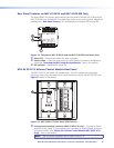
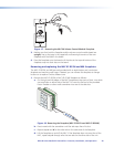
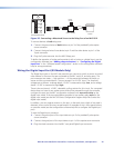
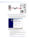
Figure 25. Connecting a Motorized Screen to the Relay Port of an MLC RS D
To connect devices to both relay ports:
1. Connect the ground wires of both devices to pin 3 of the provided 3-pole captive
screw connector.
2. Connect the signal wire of one device to pin 2 and the other device to pin 1 of the
3-pole connector.
3. Plug the 3-pole connector into the MLC Relays port.
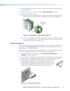
To define the operation of a relay and associate it with a button or a digital input, use the
configuration software (see “Adding relays to buttons” or “Configuring the Digital
Input Port” in the “Software-based Configuration” section or the configuration software
help for setup procedures).
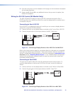
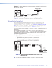
Wiring the Digital Input Port (RS Models Only)
The Digital Input port on the MLC rear panel lets you connect a switch or sensor to control
other devices in the room that are connected to the MLC serial, IR, and relay ports. This
port measures two states — high and low — of the connection between the switch or
sensor and the connected device. The port accepts 0 to 24 VDC input. The threshold
voltages are as follows: a voltage below 1.0 VDC is measured as logic low, and a voltage
above 1.5 VDC is measured as logic high.
There is also an internal, +5 VDC, selectable, pull-up resistor for this circuit. If a connected
device does not have its own power source and will be powered through the controller,
configure this port (via the MLC configuration software) with Input with Pullup as the
digital input mode. If the connected device provides its own power, select Input for the
digital input mode (see the MLC 60 Series Configuration Program Help File to select the
digital input mode).
In addition, you can program actions on this port, so that each time a high or low state is
detected, one or more functions are performed. An example of this is front panel lockout,
or executive mode (see the configuration software help file to configure the Digital Input
port).
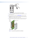
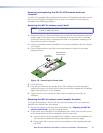
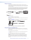
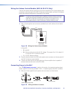
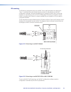
To wire the Digital Input connector:
1. Connect the ground port of the input device to pin 2 of a provided 2-pole captive
screw connector.
2. Connect the signal port of the input device to pin 1 of the captive screw connector.
3. Plug the wired connector into the MLC rear panel Digital Input connector.
MLC 60 Series MediaLink Controllers • Features, Installation, and Operation 24