


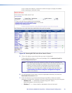
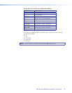

Command
ASCII Command
(Host to Unit)
Response
(Unit to Host)
Additional Description
Query LED status
View LED status
E
LC
} X5)
]
X5)
is a 32-digit number, of
which each digit represents the
status of an LED on the MLC
front panel.
On MLC 62 models, the LEDs are numbered as follows:
1 =Transmit red
2 = Transmit green
3-6 = Display text LEDs 1 through 4
7 = Button row 1, rst LED
8 = Button row 1, second LED
9-12 = Volume text LEDs 1 through 4
13-17 = Volume LEDs 1 through 5
18 = Button row 2, rst LED
19 = Button row 2, second LED
20 = Button row 3, rst LED
21 = Button row 3, second LED
22 = Button row 3, third LED
23 = Button row 4, rst LED
24 = Button row 4, second LED
25 = Button row 4, third LED
26-32 = Not used (Their status is always 0)
In
X5)
, the LEDs are represented
in descending order from 32
to 1; that is, the rst digit
represents LED 32, the second
digit represents LED 31, and
so on. The last digit represents
LED 1. Each digit in
X5)
can be
0 through 4, representing the
following possible LED statuses:
0 = off
1 = dim
2 = on (bright)
3 = slow blink
4 = fast blink
NOTE: Dual sized buttons, such as the input buttons on the MLC 62 IR D, each take up an entire button row and have
three LEDs apiece.
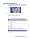
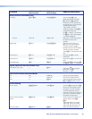
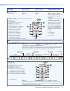
Example (MLC 62)
E
LC
}
00000001111121100000111124111104
]
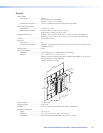
(This example is illustrated in the diagram below.)
In this LED status number, for example, the rst digit on the right (LED 1) represents the red
Transmit LED. Its status is 4, which indicates that it is blinking rapidly. The LEDs behind the
display text (3 through 6) have a status of 1, which means they are dimly lit.
Transmit
Red
10000000 1111000001121111 24 1111
40
Not used
Transmit Green
Behind “Display” Text
Buttons 1 and 2
(Button Row 1)
Behind “Volume” Text
Volume Indicators
Buttons 3 and 4
(Button Row 2)
Buttons 5 and 6
(Button Row 3)
Buttons 7 and 8
(Button Row 4)
32 31 30 29
28
LED
No.
27 26 25 24 23 22
21
20 19 18
17
16 15 14 13 12 11 10 98765
4
321
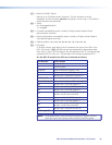
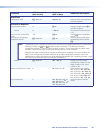
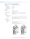
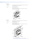
On the MLC 64, the LEDs are numbered as follows:
1 =Transmit red
2 = Transmit green
3-6 = Display text LEDs 1 through 4
7 = Button row 1, rst LED
8 = Button row 1, second LED
9-11 = Button row 2, LEDs 1 through 3
12-14 = Button row 3, LEDs 1 through 3
15-17 = Button row 4, LEDs 1 through 3
18-20 = Button row 5, LEDs 1 through 3
21-32 = Not used (Their status is always 0.)
Example (MLC 64)
E
LC
}
00000000000011111111122231111103
]
In this MLC 64 example, the red Transmit LED shows status 3 (blinking slowly). The LEDs
behind the Display text show status 1 (dimly lit). LEDs 9, 10, and 11 show status 2 (brightly
lit) because the PC button (row 2) is active.
VOLUME
DISPLAY
Extron
PC
VIDEO
LAPTOP
MUTE
ON
OFF
1
2
7
6
–
3
8
17
–
13
12
–
9
18
19
22
21
20
25
23
24
DISPLAY
Extron
ON OFF
1
2
9
12
15
18
PC
LAPTOP
VIDEO
AUX
16
13
10
7
6
–
3
8
11
14
17
19
20
MLC 60 Series MediaLink Controllers • SIS Control 61