


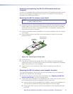

Wiring the Volume Control Module (MLC 64 RS VC D Only)
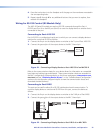
Connect the remote volume control port of an Extron amplifier to the 3-pole captive screw
connector on the rear panel of the MLC 64 volume control module, as shown in the figure
below. No software configuration is required for this module.
NOTES: • Choose an Extron amplifier that is capable of remote volume control and
muting. Not all Extron amplifiers have remote volume control ports. The
MPA 122 or MPA 401 are examples of the type of amplifier to use.
• Use shielded cable for audio connections to avoid inducing noise.
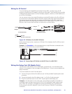
1. Wire a 3-pole captive screw connector (provided) to an audio cable as shown below:
Amplifier
Rear Panel
MLC 64 VCM
Rear Panel
10V
Vol/Mute
123
A B C
10 V
Vol/Mute
Ground
GND
VOL
10V
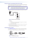
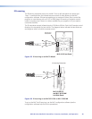
Figure 28. Wiring the Volume Control Module
In figure 28:
• A = ground
• B = Volume and mute control with DC voltage. The range is 0 to 10 V, where 0 V
is mute and 10 V is maximum volume.
• C = 10 VDC reference voltage
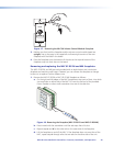
2. Plug the wired connector into the 3-pole captive screw connector on the rear panel of
the MLC 64 volume control module.
3. Connect the other end of the audio cable to an Extron amplier that is capable of
remote volume control (such as the XPA 1002).
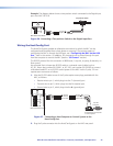
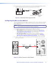
Connecting Power to the MLC
See “f PWR (power) connector,” earlier in this section, for important cautions about
power supplies. Connect the provided 12 VDC, 1 A power supply to the MLC as follows:
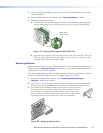
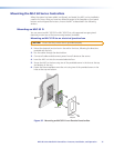
1. Wire one of the supplied 2-pole captive screw connectors as shown below.
SECTION A–A
Ridges
Smooth
Power Supply Output Cord
AA
3/16” (5 mm) Max.
Figure 29. Wiring the Power Connector
MLC 60 Series MediaLink Controllers • Features, Installation, and Operation 26