


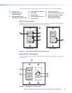
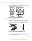
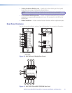
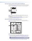

Front panel features
a
Activity LED — This bicolored LED lights green when the MLC front panel buttons
are pressed. It blinks red while enabling front panel lockout (executive mode).
b
Display power On and Off buttons — After configuring these buttons, use them
to turn the connected display device or switcher on and off.
The face of the On button contains a nub (
j
), which helps you to identify the button
by touch. When the On button is pressed, it blinks rapidly while the connected device
is warming up. When the Off button is pressed, it blinks slowly while the device
is cooling down. When this delay period has elapsed, the power button that was
pressed remains brightly lit.
By default, only one of these two buttons can be selected (active) at once. Using the
MLC configuration software, you can associate other functions and relays with each
of these buttons (see the configuration software help file).
c
Volume buttons and LEDs (MLC 62 models only) — Use these buttons to adjust
the audio volume. Each Volume button flashes when pressed and continues to flash
while being held.
The volume indicator LEDs above the buttons give indications of change to the volume
level as follows:
• When the RS-232 or IR/S port has been congured with a serial driver that
contains a volume table, the ve LEDs light in order from left to right to show
volume level increments.
• If the current driver does not contain a volume table, the rst two LEDs on the left
blink each time the Volume Down button is pressed, and the last two LEDs on the
right blink each time the Volume Up button is pressed, indicating a volume level
decrement or increment.
d
Input selection buttons — These buttons can be used to select the desired audio or
video input for the connected device or for a variety of other functions. By default the
buttons are set up as follows:
• MLC 62 RS models: Three of these buttons are set to input mode, meaning that
they are a mutually exclusive group and only one of the buttons can be selected
(active) at a time. The active input button remains brightly lit, while all other input
buttons remain dimly lit. The fourth button, labeled Mute, is set in Toggle mode
and is not grouped with the others.
• MLC 62 IR D: Two double-sized buttons are grouped in input mode and are
mutually exclusive.
• MLC 64 RS: Four double-sized buttons are grouped in input mode and are
mutually exclusive.
You can change this button behavior by using the configuration software to change
the operating mode of the button (see the MLC 60 Series configuration program help
file for more information).
e
Reset LED — Indicates the status of a reset in progress.
f
Reset button — Press this reset button to initiate factory firmware or configuration
resets (see “Resetting the MLC Using the Reset Button,” later in this section).
MLC 60 Series MediaLink Controllers • Features, Installation, and Operation 12