


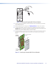
4. Press the two buttons into the faceplate until the pegs on the membrane are seated in
the corresponding holes.
5. Repeat steps 2 through 4 for any additional buttons that you want to replace, then
reattach the faceplate.
Wiring for RS-232 Control (RS Models Only)
The MLC 60 Series RS models can send out RS-232 commands through the Port A
RS-232 port (Port A) or the IR/S port (Port B) to control a display device or switcher that is
connected to the port.
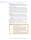
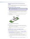
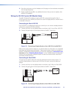
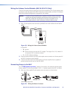
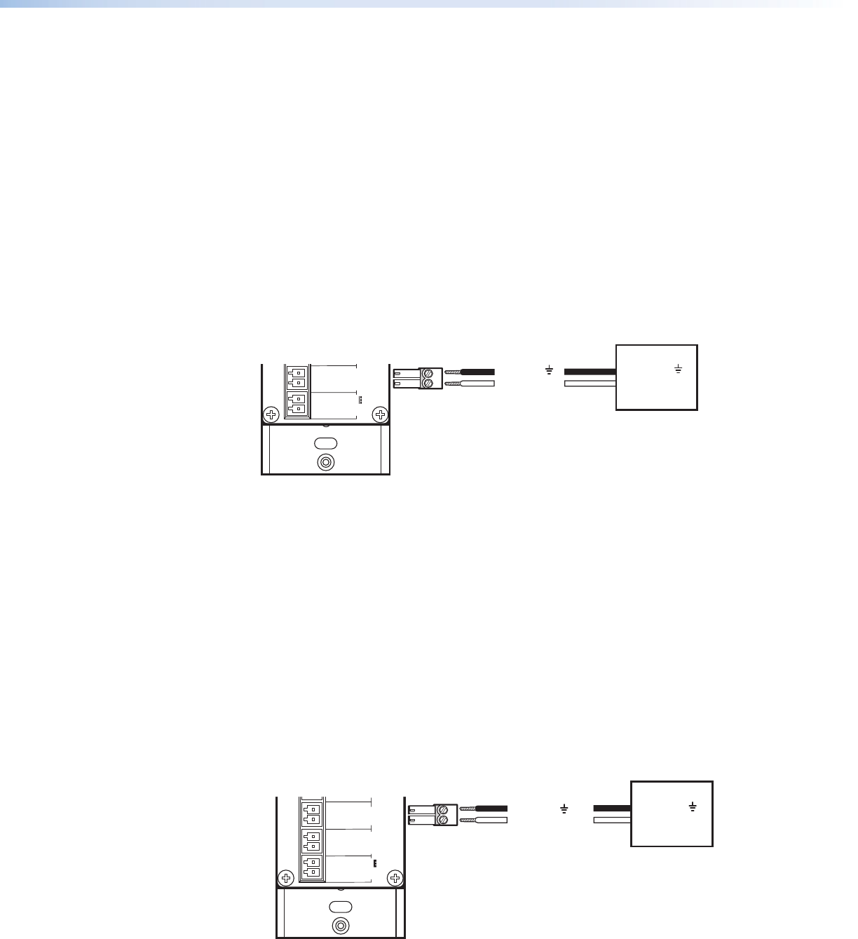
Connecting to Port A RS-232
Port A RS-232 is a unidirectional serial port to which you can connect a display device or
switcher for control via RS-232 as follows:
1. Connect the Rx pin on the display device or switcher to the Tx pin of Port A RS-232.
2. Connect the ground pin of the output device to the MLC Ground pin.
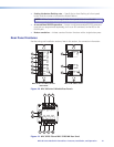
MLC RS D Rear Panel
Rx
Tx
GROUND
Tx/IR
COMMON
1
1
2
HOST/
CONFIG
PORT A
RS-232
PORT B
IR/ S
DIGITAL
INPUT
Tx
PWR
12V
0.4 A MAX
RELAYS
N/O
GROUND
GROUND
GROUND
GROUND
+12 VDC
Ground ( )
Transmit (Tx)
Ground ( )
Receive (Rx)
Display Device
Figure 21. Connecting a Display Device to Port A RS-232 of an MLC RS D
Refer to the communication sheets for your device drivers for information on compatible
baud rates and cabling type and distance. These communication sheets are accessed via
the MLC configuration software and also on the Extron web page at www.extron.com,
Download tab (see “Obtaining Device Drivers” in the “Software-based Configuration”
section or the configuration program help file to view the communication sheets and
download the device drivers).
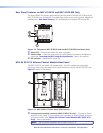
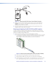
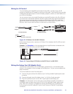
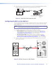
Connecting to Port B IR/S
This port can be used for either IR or RS-232 unidirectional serial communication. To
control a display device or switcher via RS-232 from this port, connect the device as
follows:
1. Connect the Rx pin on the display device or switcher to the Tx/IR pin of Port B IR/S.
2. Connect the ground pin of the output device to the MLC Ground pin.
MLC RS D Rear Panel
Rx
Tx
GROUND
Tx/IR
COMMON
1
1
2
HOST/
CONFIG
PORT A
RS-232
PORT B
IR/ S
DIGITAL
INPUT
Tx
PWR
12V
0.4 A MAX
RELAYS
N/O
GROUND
GROUND
GROUND
GROUND
+12 VDC
Ground ( )
Transmit (Tx/IR)
Ground ( )
Receive (Rx)
Display Device
Figure 22. Connecting a Display Device to Port B IR/S of an MLC RS D
MLC 60 Series MediaLink Controllers • Features, Installation, and Operation 22