


g
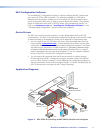
USB configuration port — Connect a USB cable (USB A to mini B) between
your computer and this port to configure the MLC via the configuration software
and to update the firmware. This port can also provide power to the MLC during
configuration.
NOTE: Do not use this port as the permanent power source for the MLC. It
should be used for power only during button and port configuration.
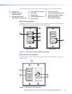
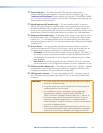
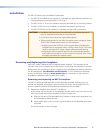
• On the MLC D models, the USB port is located at the right edge of the front
panel behind the wallplate. To access this port after installation, you must remove
the wallplate from the unit.
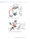
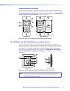
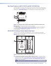
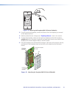
• On the MLC 62 EU and MK, the USB port is located on the left side panel. To
access this port after installation, you must detach the MLC from the installation
surface.
h
DIP switches — Reserved for future use
i
IR Learning sensor — This sensor enables the MLC to learn IR commands from the
hand-held remote control of a display device or switcher. The IR-learned commands
are used to create an IR driver, then configured to be played back with any button
press (see “IR Learning,” later in this section).
NOTE: Before performing IR Learning to create a driver, check to see if an Extron
driver exists for your device (see “Obtaining Device Drivers” in the
“Software-based Configuration” section).
j On button Identication nub — Power On button face contains a raised nub that
helps you to identify the On button by touch in a dark or dimly lit room.
k Mute button (MLC 64 only) — Press this toggle button to mute and unmute the
volume on the Extron amplifier connected to the volume control module.
l Volume control knob (MLC 64 only) — Rotate this knob to increase or decrease the
volume on the Extron amplifier connected to the volume control module.
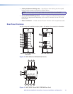
Buttons
The front panel button illumination provides status on what the MLC is doing. The buttons
are lit while the MLC has power. When a button has been pressed and is active or on, it
lights brightly. While a button is inactive or off, it is lit dimly.
When buttons are grouped together, only the button that is pressed lights brightly. The
other buttons in the group remain dim. (See the configuration software help file for
information on grouping buttons; see “Installing the Configuration Software” in the
“Software Configuration and Control” section to obtain the software.)
You can remove buttons and replace them with buttons having different labels. You can
then configure the new buttons with the functions that their labels represent, using the
configuration software (see the MLC 60 Series configuration program help file for detailed
procedures for configuring the buttons).
Each Display On/Off and input selection button can be set up to perform a sequence of
several functions, which can be combinations of the following options:
• A driver operation — Execute an RS-232 or IR control command that is part of a
device driver (for a projector, VCR, DVD player, switcher, and so forth).
• A relay operation — Execute a relay command to a room device such as a motorized
screen or a projector lift.
• Setting a time delay — Insert delays between executed commands.
MLC 60 Series MediaLink Controllers • Features, Installation, and Operation 13