


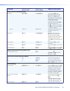
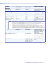

Using the Command and Response Table
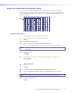
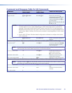
The Command and Response Table on the following pages lists valid ASCII command
codes, the responses of the MLC to the host, and a description of the command function
or the results of executing the command. The ASCII to HEX conversion table below is for
use with the table.
ASCII to Hex Conversion Table
•
Space
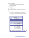
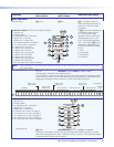
Symbol Definitions
]
= CR/LF (carriage return with line feed) (hex 0D 0A)
}
= Soft carriage return (no line feed) (hex 0D; web | )
• = Space
E
= Escape key (hex 1B; web W)
X!
= Button number: 01, 02, 03, 04, 05, 06, 07, 08, 09, or 10
Buttons are numbered from front panel top left (01) to bottom right (10).
NOTE: The Mute button on the MLC 64 VC D cannot be configured; therefore, it has
no number.
X@
= Relay port number
1 = Relay 1
2 = Relay 2
X#
= Pulse length in increments of 0.5 seconds. The default is 1 (0.5 seconds).
1 = 0.5 seconds
2 = 1 second
...
255 ≈ 130 seconds
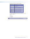
X^
= Digital input state
0 = low
1 = high
X*
= Firmware version number (displayed to two decimal places: n.nn)
X(
= Volume range level (a 3-digit number; for serial drivers with volume tables
only)
NOTE: Only positive values are allowed. The volume table levels start with zero.
X1!
= Lockout (executive) mode
0 = Off
1 = On
MLC 60 Series MediaLink Controllers • SIS Control 55