


2-27
Application Tutorials
Tutorial 8: Display the Data Pattern
Tutorial 8: Display the Data Pattern
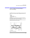
The eye-diagram analyzer can display the data pattern. This is done by select-
ing the pattern mode and triggering the display trace update on the pattern
trigger. This insures the trace on the screen remains the same from sweep to
sweep. In this mode, trace averaging can be used for more repeatable mea-
surements on noisy signals.
Masks and limit lines can be used with the pattern mode and are useful for
testing specific portions of the data sequence for mask or template violations.
This can uncover violations that happen only when a specific pattern of ones
and zeros occur. The compatible mode is Pattern.
Select Pattern Mode
1 Press INSTR PRESET.
2 If you are using an 70841A/B pattern generator, connect the TRIGGER OUT
signal to the 70820A module’s RF INPUT 2 connector.
This procedure uses the eye-diagram analyzer’s pattern mode. In pattern
mode, the trigger signal must come from the TRIGGER OUT and not the
CLOCK OUT connector. The pattern mode only works with a pattern trigger,
and not with a clock signal. The pattern trigger is derived from the clock signal
divided by the pattern length.
3 Select the pattern mode by pressing:
Setup, diagram, PATTERN
Notice the CH2 is: softkey label has changed to indicate that the trigger source
is connected to the TRIGGER OUT signal.
4 Select the bit interval and the delay by pressing:
BIT INTVL and enter 20, Traces
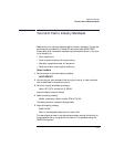
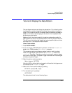
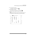
5 Turn autoscaling on by pressing:
AUTO-SCALE
The display should look like the following figure.