


Application Tutorials
Application Tutorials
Application Tutorials
This chapter contains nine tutorials that introduce important eye-diagram
analyzer features. The tutorials should be performed in the order listed. To
create the data signal, you will need a pseudo-random binary sequence
(PRBS) pattern generator. Refer to “Configure the Data Signal” on page 2-2
before you start the tutorials. You will find the following topics in this chapter:
• Tutorial 1: Measure Eye-Parameters 2-4
• Tutorial 2: Measure in Optical Power Units 2-8
• Tutorial 3: Measure Extinction Ratios on Low-Level Signals 2-10
• Tutorial 4: Measure Laser Turn-on Delay 2-13
• Tutorial 5: Use Software Filters 2-15
• Tutorial 6: Test to Industry Standards 2-19
• Tutorial 7: Default and Custom Mask or Limit Line Testing 2-23
• Tutorial 8: Display the Data Pattern 2-27
• Tutorial 9: Constructing a Low-Pass Filter from a Transfer Function 2-30
• Tutorial 10: Create a Vertical Histogram 2-36
• Tutorial 11: Create a Horizontal Histogram 2-41
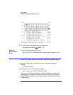
Configure the Data Signal
The following list shows typical settings that can be used for the data signal.
The list assumes you are using an 70841A/B pattern generator. The exact set-
tings depend upon the system you are using. If the system includes an
70841A/B pattern generator, use the pattern generator’s status screen to enter
these values. The procedure for viewing the status screen is explained in
“Controlling an 70841A/B Pattern Generator” on page 1-24.
• In the select pattern menu:
Pattern: PRBS 2^7-1
• In the dat o/p err-add menu:
Data Ampl: typically 800 mV to 2 V (depending on laser)
Data Hi-Lvl: 0 V (depending on laser)
• In the trg o/p clk o/p menu: