


1-13
Getting Started
Steps for Setting Up Eye-Diagram Analysis
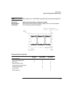
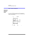
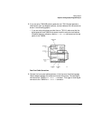
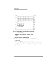
2 If you are using 70841A/B pattern generator and 70311A signal generator
modules with your eye-diagram analyzer, connect cables to the instruments as
shown in the following graphic.
• If you are using a clock source other than an 70311A, make sure that the
signal generator and 70820A microwave transition analyzer module share
the same frequency reference. Use the 10 MHz REF connectors on the rear
panel of the 70820A.
Rear-Panel Cable Connections
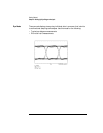
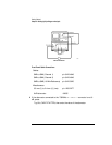
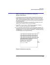
3 Connect the front-panel cables as shown in the figure on the following page.
Use an adapter between the cables and channel connectors. The data signal
connects to the 70820A’s RF INPUT 1 connector. The trigger or clock signal
connects to the 70820A’s RF INPUT 2 connector.