


3-8 (E)
HDCU-950 IMM
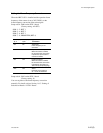
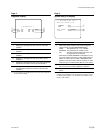
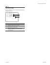
* DTX Diag *
Return Setting:Remote
Return Delay :1Field
RET4(VBS) :ON
Return FC mode:Auto
PLD V1.00 Config Done
DTX Mode Normal
1
2
3
4
5
6
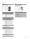
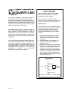
* DRX Diag *
CB Select
Bar-16:9(100%)
PLD V1.00 Config Done
DRX Mode Normal
1
2
3
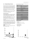
3-3. Character Display Function
Page 10
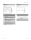
DTX Diag Dispaly
Displays the details of self-diagnosis of the DTX-1 board
of the unit.
No. Contents
1 Setting state of S605 on the DTX-1 board (HD/SD/
Remote)
*6
2 Setting state of the phase (setting of S607-1 on the DTX-
1 board) with the SD return signal during up-conversion
(SYS/MIN)
*6
3 Setting state whether the PROMPTER connector on the
rear panel is used or not with REM4 (setting of S607-2 on
the DTX-1 board) (ON/OFF)
*6
4 State of the frame frequency conversion mode (setting of
S606 on the DTX-1 board) of the return signal (Through/
A/B/Auto)
*6
5 Displays the state of the PLD (IC401 on the DTX-1
board) version and PLD. (Config Done/Config NG)
Config Done :PLD (IC401 on the DTX-1 board) started
correctly.
Config NG : PLD (IC401 on the DTX-1 board) did not
start correctly.
6 State of the operation mode on the DTX-1 board (Normal/
Test)
*6 : For details, refer to Section 1-6-5. “Setting of Switches on Boards _
DTX-1 Board”.
Page 11
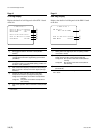
DRX Diag Dispaly
Displays the details of self-diagnosis of the DRX-1 board
of the unit.
No. Contents
1 Setting state of the HD output color bar (setting of S205
on the DRX-1 board)
*7
2 Displays the state of the PLD (IC401 on the DRX-1
board) version and PLD (Config Done/Config NG)
Config Done : PLD (IC401 on the DRX-1 board) started
correctly.
Config NG: PLD (IC401 on the DRX-1 board) did not
start correctly.
3 State of the operation mode on the DRX-1 board
(Normal/Test)
*7 : For details, refer to Section 1-6-4. “Setting of Switches on Boards _
DRX-1 Board”.