1-20 (E)
HDCU-950 IMM
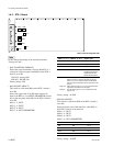
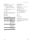
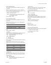
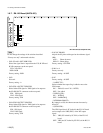
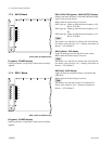
1-6-7. EN-145 Board (HKCU-951)
n
Do not change the settings of the switches described
“Factory use only” and unused switches.
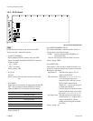
. S101 (SD ANA OUT RGB/YCD)
Selects the signal that is output from the Y/G, B-Y/B and
R-Y/R connectors on the rear panel.
YCD : Y/B-Y/R-Y
RGB : RGB
Factory setting : RGB
. S102
Not used.
Factory setting : A
. S103 (SDI A OUTPUT SDI/VBS)
Selects either SDI signal or VBS signal to be output to
the SD SDI OUT1 connector on the rear panel.
SDI : SDI signal
VBS : VBS signal
Factory setting : SDI
. S104 (SDI B OUTPUT SDI/VBS)
Selects either SDI signal or VBS signal to be output to
the SD SDI OUT2 connector on the rear panel.
SDI : SDI signal
VBS :VBS signal
Factory setting : SDI
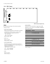
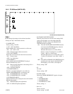
AB C D E F G H JK
1
2
3
4
5
S102
S104
S103
S402
S401
S101
S105
S201
S107
S106
EN
POWER
LEVEL
SYNC
CHROMA
COMPONENT
VBS
SC PHASE
R/R-Y
G/Y
ADV
DELAY
B/B-Y
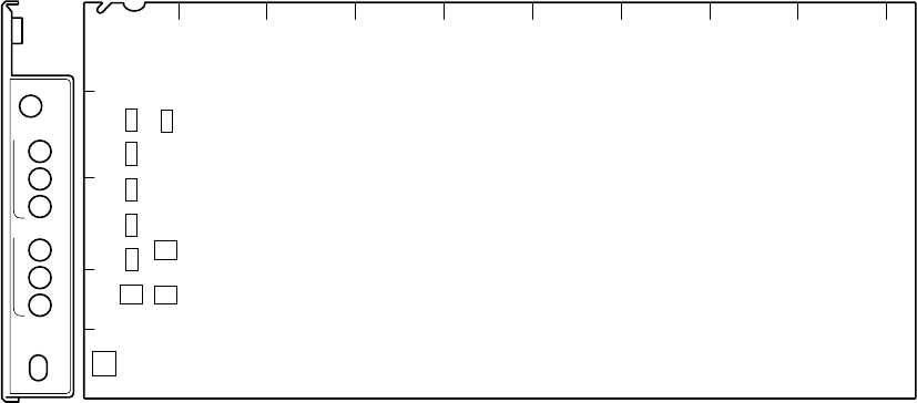
EN-145 board (A side/panel side)
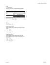
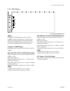
. S105 (SC PHASE)
Adjusts the SC phase with regard to the reference signal
(BB).
ADV : Phase advances
DELAY : Phase delays
Factory setting : CENTER
. S106-1 to 4
Factory use only
Factory setting : All OFF
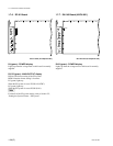
. S107
Factory setting : All OFF
-1 (ASPECT-F) :
Selects whether the aspect flag is added or not to the
VBS output.
ON : Added (in case if 16 : 9 NTSC)
OFF : Not added
-2 (WIDE-Q FIL) :
ON : WIDE-Q
OFF : NARROW-Q
-3 (CHROMA BOOST) :
By setting it to ON, the chroma amount increases by
about 2%.
-4 (WFM-VBS) :
The VBS signal that is SC-locked in the EN-145 board
can be output as the VBS (ENC) of the WF output
signal.
ON : VBS (SC-locked by SC-PLL) of the EN-145
board.
OFF : VBS (not SC-locked by SC-PLL) of the RC-91
board.
1-6. Setting of Switches on Boards


