


1-14 (E)
HDCU-950 IMM
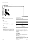
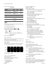
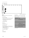
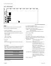
1-6-4. DRX-1 Board
AB C D E F G H JK
1
2
3
4
5
S205
S204
S201
S202
S206
S203
DRX
POWER
CHARACTER
60
50
48
540P
REW
FF
PsF
n
Do not change the settings of the switches described
“Factory use only”.
. S201 (GRAY ON/OFF)
When you turn off the power of the camera or when the
communication with the camera is cut, this switch
selects the signal to be output from the CCU.
ON : Gray signal
OFF : Color bar signal
Factory setting : OFF
. S202-1 to 8
Factory use only
Factory setting : All OFF
. S203 (CHARACTER)
The character page to be mixed into the signal that is
output from the MONI connector on the rear panel, can
be changed with REW/FF.
REW :Returns to previous page.
FF : Goes to next page.
Factory setting : CENTER
. S204
Factory use only
Factory setting : 0
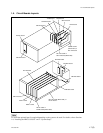
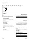
DRX-1 board (A side/panel side)
. S205 (CB SEL)
Selects the color bar signal that is output from the HD
SDI OUT 1 and 2 connectors (of the HDCU-950/HKCU-
953) on the rear panel.
Setting switches Color bar
0 16 : 9-100%-CB (non-sprit) BAR
1 16 : 9-75%-CB (non-sprit)
2 4 : 3-100CB (non-sprit)
3 4 : 3-75%-CB (non-sprit)
4 16 : 9 SMPTE-CB (_I, +Q)
5 16 : 9 SMPTE-CB (0%)
6 4 : 3 SMPTE-CB (_I, +Q)
7 4 : 3 SMPTE-CB (0%)
8 Multi Format-A ARIB-75%-SMPTE-CB
9 Multi Format-B ARIB-100%-SMPTE-CB
A Multi Format-C ARIB-CB (+I)
B Multi Format-C SMPTE-CB (_I, +Q)
Factory setting : 0
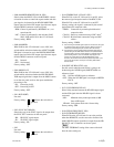
1-6. Setting of Switches on Boards