


1-33 (E)
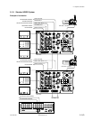
HDCU-950 IMM
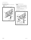
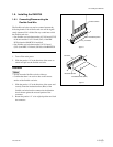
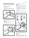
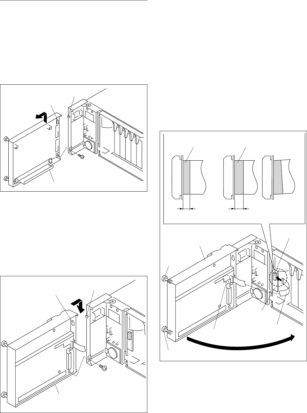
11. Connect the flexible card wire to the connector (CN2)
of the AU-281 board.
m
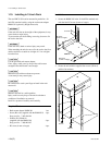
. Do not insert the flexible card wire sideways. Insert
it securely to the deep end as shown in the Fig 1.
If the connection is not performed correctly, it may
cause an failure.
. Life of flexile card wire will be significantly short-
ened if it is folded. Be very careful not to fold the
flexible card wire.
. Install the connector so that the excessive force is
not given to it.
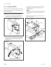
12. Close the front panel of the RM-B750 in the direction
of the arrow and secure it with the two screws (with
drop-safe).
13. Upon completion of front panel installation, check that
the switch S206 (CCU-PW) on the MPU-124 board of
the RM-B750 is ON.
n
The switch S206 (CCU-PW) on the MPU-124 board is
the power ON/OFF switch for the RM-B750. If it is set
to OFF, the panel functions are stopped.
Front panel of
the RM-B750
Potbellied hole
Pin
B3 x 5
S206
Front panel of
the RM-B750
AU-281 board
CN2
Flexible card wire
Screw
(with drop-safe)
Screw (with drop-safe)
Insulated surface (Blue) Insulated surface (Blue)
7.5 mm or less 7.5 mm or more
Fig. 1
OK
NG
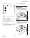
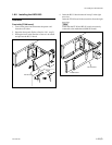
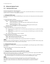
Installing the Front Panel to the Unit
5. Turn off the power and disconnect the plug from the
outlet.
6. Open the front panel of the unit.
(Refer to Section 1-8-1. step 2)
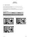
7. Remove the screw.
8. Slide the front panel in the direction of the arrow to
extract the pin from the potbellied hole and remove the
front panel.
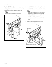
9. Insert the pin into the potbellied hole of the front panel
of the RM-B750 removed in step 4 and slide the pin in
the direction of the arrow.
n
Confirm that the pin is hooked to the potbellied hole so
that front panel does not drop.
10. Secure the front panel of the RM-B750 with the screw
removed in step 7.
Front panel
Potbellied hole
Pin
B3 x 5
1-9. Installing the RM-B750