


3-4 (E)
HDCU-950 IMM
EX
1A F:CLS
2
1
4
3
EX
White Black
R: 0 R: 0
G: 0 G: 0
B: 0 B: 0
M: 0
BLK
γ
Flare
0 OFF R: 0
Detail G: 0
1 ON B: 0
1A F:CLS
* System Status *
HDC-950 1080/59.94I
Gen Lock : SD
DRX:1080/59.94I
FC :1080/59.94I
RC : 525/59.94I
RET1:HD SDI 59.94I
2:HD SDI 59.94I
3:HD SDI 59.94I
4:SD VBS SQ
1
2
3
4
5
6
7
8
9
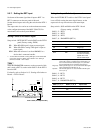
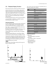
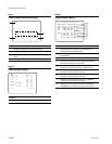
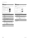
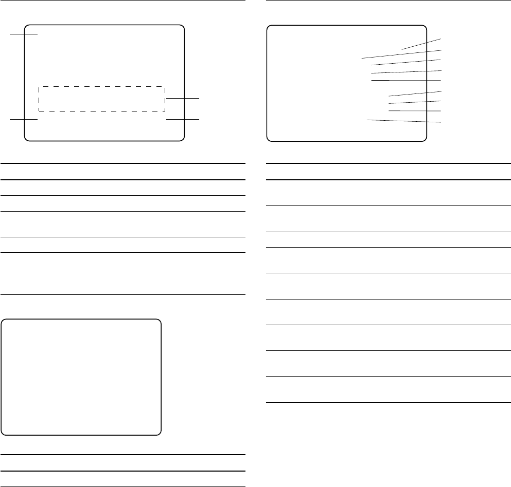
3-3. Character Display Function
Page 1
Camera Lens/Filter Status Display
No. Contents
1 Displays the setting state of the lens extender.
2 Displays the setting state of the ND filter and CC filter.
3 Displays the message when the optical reception level
lowers.
4 Displays the setting state of the aperture of the lens.
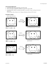
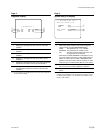
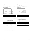
Page 2
Camera Status Display
Contents
Displays information of White/Black/Black γ/Flare/Detail, etc.
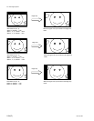
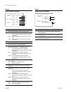
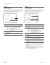
Page 3
System Status Display
No. Contents
1 Displays the type of camera connected to the unit.
(HDC-950/HDC-930/UNDEFINED)
2 Displays the type of external sync signal.
(Free/SD/HD)
3 Displays the setup format of the DRX-1 board.
*1
4 Displays the setup format of the board mounted in the
fifth slot from the left of the front side.
*1
5 Displays the setup format of the board mounted in the
sixth (right most) slot from the left of the front side.
*1
6 Displays the type of signal that is input to the RET 1
connector on the rear panel of the unit.
7 Displays the type of signal that is input to the RET 2
connector on the rear panel of the unit.
8 Displays the type of signal that is input to the RET 3
connector on the rear panel of the unit.
9 Displays the type of signal that is input to the RET 4
(PROMPTER) connector on the rear panel of the unit.
*1 : For details, refer to Section 2, “System Setup”.