


2-12 (E)
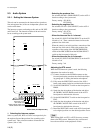
HDCU-950 IMM
1
2
3
4
5
6
0
7
8
50
5
1
2
3
4
5
6
1
7
8
61
6
1
2
3
4
5
6
2
7
8
72
7
1
2
3
4
5
6
3
7
8
83
8
1
2
3
4
5
6
4
7
8
94
9
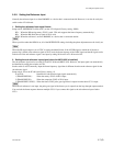
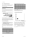
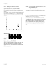
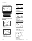
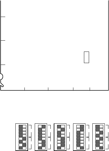
(Example of setting)
First digit
Second digit
Camera
number
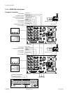
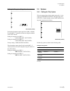
2-4-2. Setting the Camera Number
System that does not use CNU-700/500
Use switch S421 on the AT-149 board to set the camera
number.
Use switches 1 to 4 to set the first digit and use switches 5
to 8 to set the second digit. “0” to “f” can be set as each
digit, but “a” to “f” are invalid. Camera numbers 1 to 96
can be set.
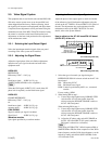
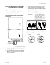
AT-149 board (A side)
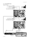
System that uses CNU-700/500
The CCU connector number on the rear of the CNU-700/
500 is the camera number. For example, the camera
number of the CCU video camera that is connected to the
CCU 1 connector is 1.
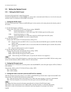
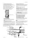
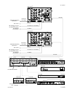
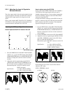
2-4-3. Connecting the Control, Intercom and
Tally Audio Signals
An example of connection is described on the next page.
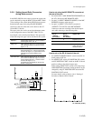
In case of cascaded connection of the DVS-V1201
SD digital video routing switcher :
Set unit address switch “5” of REMOTE2 of the DVS-
V1201 SD digital video routing switcher to ON and set the
other switches to OFF. For cascaded connection of the
DVS-V1201 SD digital video routing switcher when at
least 13 cameras are used, set unit address switch “6” of
the second camera to ON and set the other switches to
OFF.
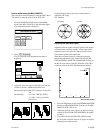
2-4. Systems
DAB C
1
2
3
4
5
S421