


2-9 (E)
HDCU-950 IMM
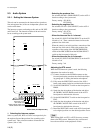
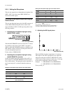
2. Setting the headset microphone
Set switch S4 (TALK GAIN) on the AU-281 board
according to the type of headset microphone to be connect-
ed to the INCOM connector on the front.
When using a carbon microphone : CARBON
(Sensitivity _20 dB, power is supplied.) (factory setting)
When using a electric condenser microphone : ECM
(Sensitivity _40 dB, power is supplied.)
When using a dynamic microphone : DYNAMIC
(Sensitivity _60 dB, power is not supplied.)
. Adjusting the TALK level
Adjust the headset TALK level with control RV401
(TALK LEV) on the AVP-4 board according to user’s
request.
. Adjusting amount of the side tone
Use the SIDE TONE control on the AVP-4 board panel and
adjust amount of the side tone to be connected to the
INCOM connector on the front according to user’s request.
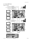
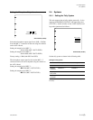
3. Setting the input level of the PGM audio signal
Set switches S500 (PGM1 SEL) and S501 (PGM2 SEL) on
the AVP-4 board to 0 dBu or _20 dBu according to each
level of audio 1 and 2 of the system.
Factory setting : 0 dBu
. Selecting the PGM audio signal
Set the PGM audio signal of the headset connected to the
INCOM connector on the front with the PGM SELECT
switch on the AVP-4 board panel according to user’s
request.
Selecting PGM 1 : PGM 1 (Factory setting)
Selecting mix of PGM 1 and PGM 2 :Mix
Selecting PGM 2 : PGM 2
.
Adjusting the mix amount of the PGM audio signal
Use the PGM 1, 2 LEVEL control on the AVP-4 board
panel and adjust mix amount of the PGM audio signal of
the headset connected to the INCOM connector on the
front according to user’s request.
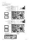
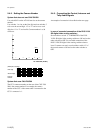
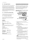
4. Selecting an intercom line to be connected to
the INCOM connector
Use the switch on the front panel to select the intercom line
to be connected to the INCOM connector on the front as
follows.
. When connecting to the producer line :
Set the INCOM SELECT switch to PROD.
. When connecting to the engineer line :
Set the INCOM SELECT switch to ENG.
. When connecting only a camera :
Set the INCOM SELECT switch to PRIV. When this
position is set, the intercom from outside is cut and the
system consists of the intercom and camera.
n
When switch S12 (INPUT INCOM SELECT) on the AVP-
4 board is set to 1 ch, the INCOM SELECT switch on the
front panel of the unit and the camera are fixed to the
producer line regardless of the setting.
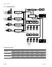
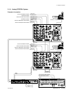
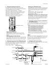
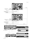
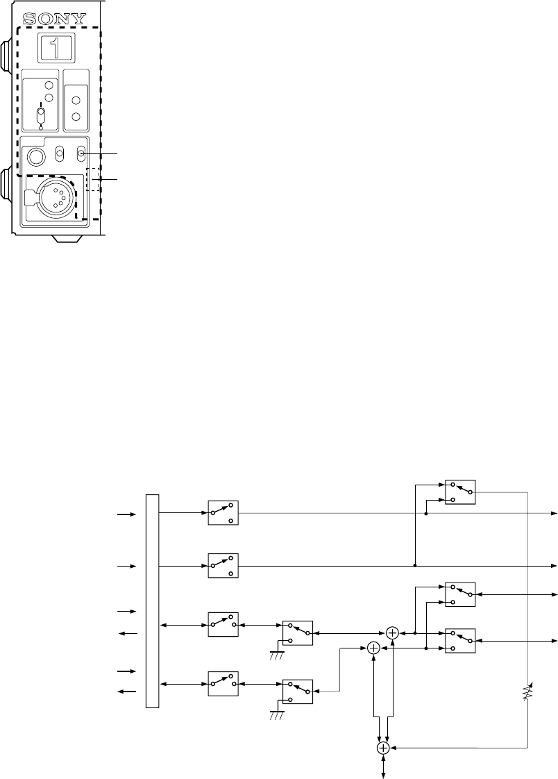
5. Setting the AVP-4 board switch
The flow of the switch setting on the AVP-4 board and the
intercom signals is as follows.
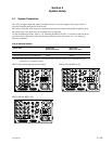
2-3. Audio System
POWER
CABLE
ALRAM
OPEN
SHORT
CAM
MAIN
INCOM MIC-ON
OFF
PGM
PROD
ENG
PRIV
S4
INCOM SELECT switch
S500
S610,611
S710,711
0dB/–20dB
S501
0dB/–20dB
4W/RTS/Clear-Com
4W/RTS/Clear-Com
PRIV(Front panel)
PRIV(Front panel)
RV201,202
ENG/PROD (Camera side)
2CH/1CH (S12)
ENG/PROD (Camera side)
2CH/1CH (S12)
4X
5
@/
8
7
5
!.
!\
3
2
1
!]
Y
G
X
Y
G
X
Y
X
Y
G
X
Y
Program line 0
X
Y
G
Program line 2
System intercom
Talk
Producer line
Receive
Talk
Receive
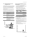
INCOM/TALLY/PGM
connector on the rearpanel
3. Select the
PGM audio input level
PGM 1
PGM 2
INCOM 1
INCOM 1
3. Set the mix amout of
PGM audio signal
INCOM SELECT switch
on board panel
4. Setting for the
INCOM connector
on the front panel
1. Select the input 4W/RTS/
Clear-Com
Engineer line
To the INCOM connector on the front panel
!'
9
!/
@=
PGM 1/PGM 2
S1