


3-5 (E)
HDCU-950 IMM
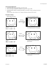
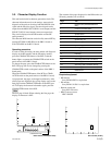
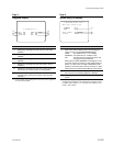
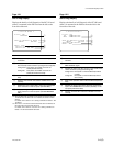
* Diagnosis *
AT :OK DRX:OK
AVP:OK FC :OK
DTX:OK RC :OK
1
2
3
4
5
6
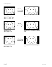
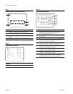
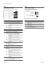
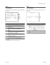
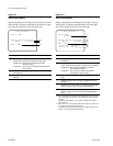
* System Diag 1/3 *
Optical Condition
CAMERA OK
CCU OK
Fan Power OK
Timer 264H
1
2
3
3-3. Character Display Function
Page 4
Diagnosis Display
No. Contents
1 Displays the self-diagnosis result of the AT-149 board
(OK/NG).
*2
2 Displays the self-diagnosis result of the AVP-4 board
(OK/NG).
*2
3 Displays the self-diagnosis result of the DTX-1 board
(OK/NG).
*2
4 Displays the self-diagnosis result of the DRX-1 board
(OK/NG).
*2
5 Displays the self-diagnosis result of the board mounted in
the fifth slot from the left of the front side (OK/NG).
*2
6 Displays the self-diagnosis result of the board mounted in
the sixth (right most) slot from the left of the front side
(OK/NG).
*2
*2 : For the contents of the self-diagnosis of each board, refer to pages 8 to
14 of the character display.
Page 5
System Diag (1/3) Display
No. Contents
1 State of the optical reception level of the camera and
camera control unit (OK/CARE/WARNING/NG)
*3
CARE: The optical level is _17 to _20 dBm.
WARNING: The optical level is _20 dBm or less.
NG: The state when the optical level is low and
any signal cannot be obtained.
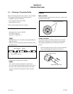
When either of CARE, WARNING or NG appears on the
CCU side, clean the connector or cable while referring to
Section 3-1. When either of CARE or WARNING or NG
appears on the camera side, clean the connector or cable
while referring to the Maintenances Manual of the camera.
2 State of the fan of the power supply block (OK/NG)
NG : The fan of the switching regulator is defective.
3 Displays the accumulated power-on hours to the AT-149
board
*3 : The optical sending/receiving level state of the main unit also can be
checked using the indicator on the panel surface of the DTX-1 board.
For details, refer to Section 1-7-5. “Functions of the Indicators on the
Boards _ DTX-1 Board”.