


2-11 (E)
HDCU-950 IMM
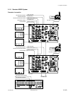
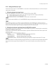
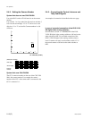
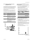
Setting the Microphone Output Level
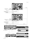
AVP-4 board (A side)
Select the microphone output signal level (0 dB, _20 dBu)
from the MIC 1, 2 connector on the rear using the switches
on the AVP-4 board.
Setting the output level of MIC 1 :
Switch S503 (MIC 1 OUT LEVEL)
Setting the output level of MIC 2 :
Switch S603 (MIC 2 OUT LEVEL)
Factory setting : 0 dBu (both S502 and S503)
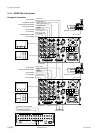
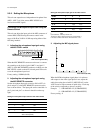
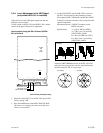
The microphone output signal level from the MIC 1, 2
connector on the rear can be adjusted using the volume on
the AVP-4 board.
Setting the output level of MIC 1 :
1RV500 (MIC 1 OUT LEVEL)
Setting the output level of MIC 2 :
1RV501 (MIC 2 OUT LEVEL)
2-4. Systems
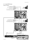
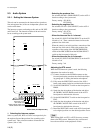
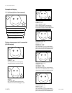
2-4-1. Setting the Tally System
This unit supports the red tally and the green tally. It also
supports the MAKING CONTACT and supplying power
(24 V/TTL). Set the switches on the AVP-4 board accord-
ing to the system used as follows :
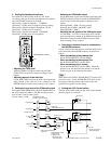
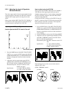
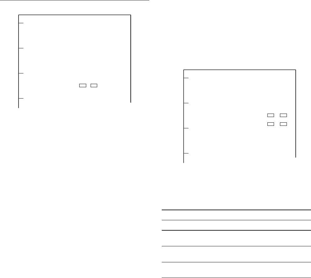
AVP-4 board (A side)
Set the tally system as shown in the following table.
Setting the tally system
Red tally Green tally
Switch S100 S102 S101 S103
MAKING CONTACT _ CONTACT _
CONTACT
Supplying POWER POWER POWER POWER
24 V power
Supplying POWER TTL POWER TTL
5 V power
Switches S100 and S101 are set to CONTACT when the unit is shipped from
the factory.
2-3. Audio System
2-4. Systems
GH JK
S502S503
1
RV501
1
RV500
GH JK
S101 S100
S102S103
GH JK