


Replaceable Parts 89
5
Replaceable Parts
INTRODUCTION
Chapter Organization
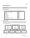
This section lists the replaceable electrical and mechanical parts for the Agilent 668xA series power supplies. (Component
location diagrams are located in Chapter 6.) The lists consist of tables organized by assemblies as follows:
Assembly See
Main chassis * Table 5-3
A1 Front Panel EBoard Table 5-4
LED Board Table 5-5
A2 GPIB Board Table 5-6
A3 FET Board Table 5-7
A4 AC Input Board Table 5-8
A5 DC Rail Board Table 5-9
A6 Bias Board Table 5-9
A7 Snubber Board Table 5-11
A8 Fast Sense Board Table 5-9
A9 Down Programming/Slow Sense Board Table 5-9
A10 Control Board Table 5-10
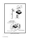
* The locations of circuit board assemblies and chassis-mounted components are shown in Fig 3-20.
Reading the Tables
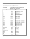
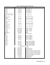
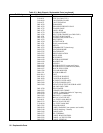
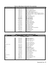
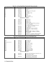
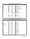
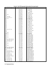
Each table lists electrical components alphabetically by reference designator and provides the Agilent part number followed
by the part description. Mechanical parts are placed after the electrical parts and listed alphabetically by part description.
Unless otherwise specified, a listed part is used in all models of the series. Model-specific parts are tabulated by model
number under the reference designator. The reference designators are defined in Table 5-1. Abbreviations used in parts
descriptions are explained in Table 5-2.
Table 5-1. Part Reference Designators
A assembly J jack SW switch
B blower (fan) K relay T transformer
C capacitor L inductor TB terminal block
CR thyristor/SCR P plug U integrated circuit
D diode Q transistor VR voltage regulator
DSP display (LCD) R resistor W cable or jumper
F fuse RT thermal resistor Y crystal oscillator
Table 5-2. Part Description Abbreviations
assy assembly M metric sq square w/o without
bd board mch machine submin subminiature xfmr transformer
blvl belleville mm millimeter thk thick xtal crystal
gnd ground mtg mounting thrd thread
lg long PCB pc board w/ with