


Principles Of Operation 85
A4 AC Input Board
The A4 Input Board contains the Inrush-Current Limit relay (K401), Main Power Relay (K402), current-limiting resistors
(R407, R408) and open-fuse-detect resistor circuit (R400-R405). On power-on, the current-limit relay (K401) closes
allowing the dc rail capacitors to charge under a controlled condition. This applies ac voltage to the A6 Bias Board. After
the turn-on initialization period (approximately 10 seconds), the main relay (K402) closes, shorting out the current-limit
resistor.
The open-fuse resistors supply partial ac voltage to the front panel LED board. An open-fuse causes an unbalanced voltage
to be supplied to the open-fuse detect circuit causing the front panel Check Fuses LED to flash. If all three fuses are good,
or if all three are open, the Check Fuse does not flash. The three-phase line inductor is connected to the A4 Input board via
J417 (Range 1, 180-235Vac) or J418 (Range 2, 360-440Vac).
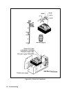
A5 DC Rail Board
The A5 DC Rail board contains the full-wave, three-phase, rectifiers and the input filter circuits. The ac mains are full-wave
rectified by D420-D425 and converted to two, 300-volt dc rails by filter capacitors, C423-C426, and by two range select
connectors. In range 1 (180-235Vac), J438 connects the two DC rails, called Rail #1 and Rail #2, in parallel. Each rail
supplies 300Vdc to the A3 FET board via J430 and J431. In Range 2 (360-440Vac), J439 connects the two DC rails in
series. Each rail still supplies 300 Vdc to the A3 FET board via J430 and J431.
The A5 DC Rail board also contains the bias transformer and primary range select connectors J436 (Range 1) and J437
(Range 2). There are two LEDS (DS420, DS421) which light when more than 40Vdc is present on the dc rails.
As a precaution always disconnect power supply from ac mains and wait 7 minutes before handling dc rail
board. Be certain that the LEDs are completely extinguished.
The +24 auxiliary bias fuse, F420, and the standard bias fuse, F421, are located on the dc rail board.
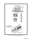
A3 FET Board
The A3 FET board consists of two power FET stages connected between the +rail and -rail voltages, and connected across
the FET stages is a chassis mounted power transformer. The entire circuit represents an H-bridge configuration. A complete
stage consists of eight, power FETs and two, bridge-driver ICs. The power FETs are mounted on but isolated from the heat
sink assembly. The two power FET stages are isolated from each other.
The DRIVElA, lB and DRIVE2A, 2B pulses, received from the A10 Control board, are used by the bridge drivers (U201,
U202, U301, U302) to derive control pulses for the FET switches. The width of the pulses determines the ON time of the
FET switches, thereby determining the magnitude of the output voltage or current. DRIVElA pulses turn on one set of
+RAIL (Q301, Q311) and -RAIL (Q303, Q333) FETs, causing current to flow through power transformer, T900, in one
direction. DRIVE2A pulses turn on the other set of +RAIL (Q304, Q344) and -RAIL (Q302, Q322) FETs causing current
to flow through T900 in the opposite direction. The FET on/off periods are controlled by the duty-cycle detect and the
peak-current detection circuits. If the output attempts to change, regulation is accomplished by the CV/CC control circuits
on the A10 Control board. These circuits vary the width of the drive pulses and the duration of the FET on/off periods.