


72 Troubleshooting
A1DSP1 LCD Display
1. Remove the A1 Front Panel Board as described in that procedure.
2. Remove the nuts securing the LCD display to the front panel assembly and remove the LCD and attached ribbon cable
(see CAUTION below). (When reinstalling this cable, be sure to line up the cable stripe over the LCD connector pin
marked with a square.)
The display connector is fragile. When removing the cable from the LCD display, carefully rock the
cable connector back and forth while gently pulling it back.
A1G1 and A1G2 Rotary Controls
1. Remove the A1 Front Panel Board as described in that procedure.
2. Remove the AlG1 and AlG2 cables from connectors A1J4 and A1J5.
3. Remove nuts securing the AlG1 AlG2 controls to the board and remove controls.
A1KPD Keypad
1. Remove the A1 Front Panel Board as described in that procedure.
2. With board removed, keypad can easily be lifted out of the Front Panel Assembly.
Output Bus Boards A7, A81 and A9 & Chassis Components
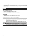
Note To remove the A7 Snubber Board, A8 Fast Sense Assembly, A9 Downprogrammer and other chassis
mounted components, first remove the A10 Control Board frame assembly and the two Rectifier Heat
Sinks described earlier. Once the heat sinks are removed you will have access to the A7, A8, and A9
boards as well as other chassis mounted components.
Should you have any difficulty in removing power supply components or boards, contact the Agilent
Technologies Support Line for help.
Shock Hazard: Hazardous voltage can exist inside the power supply even after it has been turned off.
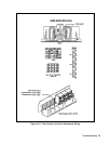
Check the INPUT RAIL LED (A4CR402) under the RFI shield (see Figure 3-18 end of this section for
LED location). It the LED is on, there is still hazardous voltage inside the supply. Wait until the LED goes
off (approximately 7 minutes after power is removed) before proceeding.