


86 Principles Of Operation
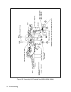
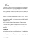
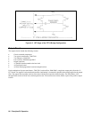
Figure 4-2. 1ST Stage of the FET H-Bridge Configuration
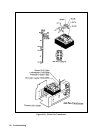
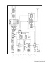
Output Circuits
The output circuits include the following circuits:
• Chassis mounted components.
• Two power transformers, T900/T901.
• Two inductors, L900/L901.
• Four rectifiers, D900 through D903.
• Output capacitors.
• A7 Snubber board mounted to the heat sink.
• A8 Fast Sense board.
• A9 Slow/Downprogrammer board and output bus bars.
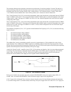
Each combination of power transformers, T900/T901, and rectifiers, D900/D903, couples the output pulses from the A3
FET board. The output of each transformer/rectifier combination is connected in parallel before being applied to the output
filter. The output filter assembly consists of bus bars with the filter capacitors bolted to them. The filter chokes, L902
through L906, consist of ferrite cores enclosing the bus bar. The current-sense resistor, R900, is part of the positive-output
bus bar.