


54 Troubleshooting
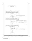
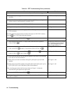
Table 3-4. FET Troubleshooting Chart (continued)
Procedure Result
Dynamic Troubleshooting
1. Turn off the power supply and remove the A3 FET Board with its heat sink
assembly.
See "Disassembly Procedures"
2. Short the collectors of Q251 and Q253 or Q351 and Q353 by connecting the
collector (case) of each transistor to common ( E507) .
3. Connect waveform generator to J200-1 and J200-2.
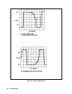
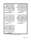
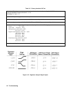
4. Set generator to produce a 20 kHz, 20V p-p triangular waveform
See Figure 3-14A.
5. Connect 15V from an external supply to E206 or E306 (positive) and E207 or
E307 (common).
e
: All of the following measurements are taken with respect to E207/E307 common,
test point
on A3 FET Board schematic diagram
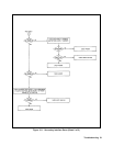
6. Check bias voltage at U203-1/U303-1 .
+5V
7. While adjusting the external 15V supply input, check the bias trip point at
U204-1/U304-1
.
Voltage goes from low (0V) to high
(5V) at an input of approximately
12V; and from high to low at an
input of approximately 13V.
8. Set external supply input to + 15V and check drive 1 waveform at
U201-10/U301-l0
and drive 2 waveform at U201-12/U301-12 .
See Figure 3-14B.
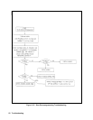
9. Check that pulses are present at U201-1 , U201-7/U301-7 and
U302-1, U202-1
, U202-7/U302-7 .
See Figure 3-14C.
10. Pulses should be present on both sides of inductors L201-204 or L301-304 and
L213-216 or L313-316 as follows:
Check the pulses on the driver transistor side (Q251-Q254/Q351-Q354) of each
inductor.
Check the pulses on the FET regulator side (Q201-Q204, Q301-Q304, Q211, Q311,
Q222, Q322, Q233, Q333 and Q244, Q344) of each inductor.
If the waveforms do not have the fast step as shown in Figure 3-14, then the
associated FET gate input has an open circuit.
See Figure 3-14D.
See Figure 3-14E.
11. Measure the VREF voltage at U205-2 .
≈ 1.7V
Check the peak current limit by connecting a 68KΩ resistor from +5V (U201-9) to
U205-3 or U304-5.
All pulses turn off.