


Troubleshooting 53
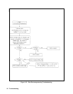
CV/CC Status Annunciators Troubleshooting
When troubleshooting the CV/CC status annunciators or status readback circuits, first measure the voltage drop across the
gating diodes, which are Al0D651 for the CC circuit and Al0D652 for the CV circuit (see A10, Sheet 2). A conducting
diode indicates an active (ON) control circuit. This forward drop is applied to the input of the associated status comparator
(A10U502) and drives the output low. The low signal indicates an active status which is sent to the secondary
microprocessor A10U506 via Programmed GAL Al0U505 (see schematic Sheet 1). The front panel CV annunciator lights
when the CV mode is active (CV is low) and the CC annunciator lights when the CC mode is active (CC is low). If neither
is active, the UNREGULATED (Unr) annunciator comes on.
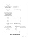
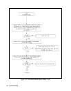
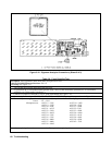
A3 FET Board Troubleshooting
Because test points on the FET board are not accessible when the board is installed, troubleshooting must be performed
with the board removed from the power supply. Both static (power removed) and dynamic (power applied) troubleshooting
procedures are provided. The location of different test points are shown by encircled numbers on the A3 FET Board
schematic and component location diagrams (see Chapter 6). There are two isolated FET bridge assemblies (see schematic
in Fig. 6-10 sheets 1 and 2). Test each FET bridge individually.
Note If any power FET (Q201-204, Q301-304, Q211, Q311, Q222, Q322, Q233, Q333, Q244, Q344) is
defective, you must replace all eight with a matched set.
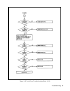
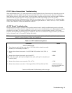
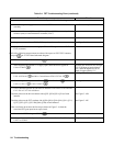
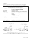
Table 3-4. FET Troubleshooting Chart
Procedure Result
Static Troubleshooting
1. Turn the power supply off and remove the A3 FET board with its heatsink assembly
attached (see "Disassembly Procedures").
2. Measure the resistance between the + Rail (E202 & E302) and the - Rail ( E201 &
E301).
≥ 20MΩ.
3. Measure the resistance between the gate of each FET
(Q201-204, Q211, Q222, Q233, Q244, and Q301-304, Q311, Q322, Q333, and Q344) and
common (-Rail).
>15KΩ.
4. Measure the resistance across capacitor C201 & C301.
≈ 150Ω.
5. Measure the resistance across the 15V bias input (E206 to E207 and E306 to E307).
≈ 1KΩ in the forward
direction and 490Ω in the
reverse direction.
Continue with Dynamic Troubleshooting on the next page