


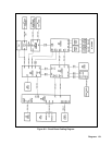

118 Diagrams
Table 6-3. Test Points (continued)
TEST POINT No. & Loc. Signal Tested Measurement and Conditions
Bias Board (continued)
U308-1
PREF
+2.5V
U308-5
RESET*
Held low for approximately 50 ms at power-on,
then goes high.
U311-7
FAN DETECT
+3V
D317
-25V +3V
U311-2
FAN_PWN
+0.6V
A3 FET Board
Test points through are on the A3 FET Board. Troubleshooting procedures at these points are given under
Dynamic Troubleshooting section of the FET Troubleshooting Chart (Table 3-4).
A10 Control Board
+C500
Secondary common (Sheet 1)
U504-6
CC/CC DACs reference (Sheet 1)
U503-7
Readback DAC reference (Sheet 1)
U513-6
CVPROG (Sheets 2,4)
U514-6
CVPROG (Sheets 2,4)
NOTE:
Measurements at test points through where taken under the following conditions:
1. Programming a. Voltage = ½ scale
b. Current = ½ scale
c. OV = full scale
2. First measurement in CV mode with no load.
3. Second measurement in CC mode with output shorted.
U621-1
VMON (Sheet 4)
U621-7
CV CONTROL (Sheet 4)
U502-2
CV* (Sheet 4)
CV mode =0V CC mode = 5V
U624-1
CC CLAMP AMP output (Sheet 4) CV mode =+2.2V CC mode = +2.2V
U622-6
1ST I AMP output (Sheet 4) CV mode =0V CC mode = -0.4V
U620-7
2ND I AMP output (Sheet 4) CV mode =0V CC mode = +4.5V
U620-1
CC CONTROL (Sheet 4) CV mode =+10V CC mode = +0.4V
U502-3
CC* (Sheet 4) CV mode =+5V CC mode = 0V
Y608-7
FAST SENSE AMP (Sheet 3) CV mode = -4V CC mode = 0V
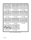
U607-7
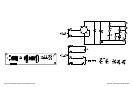
RAMP GEN (Sheet 3) See Figure 6-1
U607-1
RAMP GEN (Sheet 3) See Figure 6-1
U602-9
DIVIDER output (Sheet 3) See Figure 6-1
U605-3
SUMMING POINT (Sheet 3) See Figure 6-1
U602-6
DEADTIME LATCH (Sheet 3) See Figure 6-1
U605-7
SUMMING COMPARATOR
(Sheet 3)
See Figure 6-1