


Troubleshooting 71
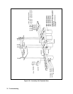
A10 Control Assembly
Disconnect the cables from the following connectors at the A10 DC RAIL board:
1. Disconnect the ribbon cable going from to the A6 Bias board. This cable connects to J509 on the A10 board but it is
easier to disconnect it at the A6 Bias Board.
2. Disconnect cables from connector J507 (phone) and connectors J510, J511, J512, and J513 on the A10 Control Board.
3. At rear of power supply, remove holding screw directly above fan. This screw holds the frame and A10 control board
in place.
4. At rear of power supply unplug connector DIG CNTL from A10 Control Board.
5. Move board to the right and lift board and associated steel frame out of chassis.
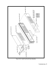
Front Panel Assembly
1. Peel off vinyl trim (one strip on each side of front panel) to access the four screws that secure the front panel assembly
to the chassis.
2. Remove the four screws (two on each side) using a size T-10 TORX.
3. Disconnect phone cable W5 from J6 on the A1 Front Panel Board.
4. Record the color code and the location of each of the four wires connected to line switch S1.
5. Disconnect the wires from the switch assembly.
6. Remove the front panel assembly.
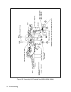
S1 Line Switch
1. Remove Front Panel Assembly and disconnect switch wires as described in that procedure.
2. Release the switch locking tabs by pressing them inward against the body of the switch and removing the switch.
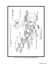
A1 Front Panel Board
1. Remove the Front Panel Assembly and disconnect the switch as described under "Front Panel Assembly".
2. Disconnect LCD display ribbon cable W2 from J2 on the A1 Front Panel Board.
Note When reinstalling the LCD ribbon cable, be sure to line up the "stripe" of the ribbon cable with pin 1
on J2.
3. Use a small Allen wrench (0.050") to loosen the set screws that are inset in the knobs. (These are the AlG1 and AlG2
Voltage/Current control shafts that extend through the front panel.) Remove knobs and shaft bushings.
Note Be careful not to unscrew the knob set screws too far out as they can easily fall out of the knob and
become lost.
4. Remove screw (if installed) that secures board to the Front Panel Assembly. The screw is located near J4 on the Front
Panel Board.
5. Lift tab (near J6 on front panel board) and slide left to release board from the A1 Front Panel Assembly and remove
board.