


Troubleshooting 69
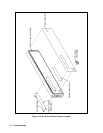
Top Cover
1. Remove the four screws that secure the carrying straps (two TORX 20 screws on each side). These same screws secure
the cover to the chassis.
2. Spread the bottom rear of the cover, and then pull the cover backwards towards the rear of the power supply to
disengage it from the front panel.
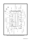
Shock Hazard: Hazardous voltage can exist inside the power supply even after it has been turned off.
Check the INPUT RAIL LED (A4CR402) under the RFI shield (see Figure 3-18 end of this section for
LED location). If the LED is on, there is still hazardous voltage inside the supply. Wait until the LED goes
off (approximately 7 minutes after power is removed) before proceeding.
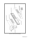
Removing Protective RFI Shield (Galvanized Sheet Metal)
Once you remove the top cover of the power supply, you will see the RFI galvanized sheet metal cover preventing the
power supply from emanating RFI fields. The RFI shield covers most components and circuit boards, as well as, many of
the chassis-mounted components. You must remove this shield in order to gain access to the inside of the power supply.
Remove the shield as follows:
1. There are approximately 21 screws holding the cover to the frame.
2. There are two screws at the top of the shield that secure a retaining clip for the GPIB board. You do not need to remove
these screws, simply loosen the screws and slide the GPIB retaining clip backwards free of the GPIB board.
3. Remove all shield securing screws using a TORX T-15 screwdriver and save for later reinstallation .
4. Lift the RF shield out of the chassis.
5. When DC RAIL LEDs are extinguished, it is safe to work inside the power supply. (See Warning note above.)
Note The following procedures describe the removal of most of the circuit boards within the power supply.
Once the GPIB board is removed, you will have access to the A4 AC Input Assembly and the A5 DC Rail
Assembly. Similarly, once the A10 control board is removed along with the Rectifier HS you will have
access to other components and boards within the supply.
It is recommended that when you disconnect any wires and/or cable connectors you should immediately
label them to simplify their reinstallation later.
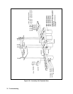
GPIB Board
To remove the GPIB board, disconnect the cables from the following connectors at the GPIB board:
1. Disconnect the cable going to connector P101.
2. Disconnect phone cable going to J107.
3. Disconnect phone cable going to J107.
4. Disconnect phone cable going to J108.
5. Remove two (2) holding screws at read of chassis holding GPIB board in place.
6. Using a 7 mm driver, remove the two (2) screws holding the GPIB connector at rear of chassis.
7. The GPIB board can now be lifted out from the chassis.