


Verification 13
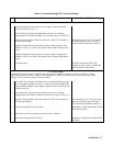
Programming The Tests
General Considerations
Procedures are given for programming these tests either from the front panel keypad or from a GPIB controller. The
procedures assume you know how to use the front panel keypad or how to program over the GPIB (see the Power Supply
Operating Manual for more information). When using computer-controlled tests, you may have to consider the relatively
slow (compared to computer and system voltmeters) settling times and slew rates of the power supply. Suitable WAIT
statements can be inserted into the test program to give the power supply time to respond to the test commands.
This power supply can provide more than 240VA at more than 2 volts. If the output connections touch each
other, severe arcing can occur resulting in burns, ignition or welding of parts. DO NOT ATTEMPT
TO MAKE CONNECTIONS WHILE OUTPUT POWER IS ON. These connections should be performed
only by qualified electronics personnel.
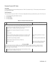
Programming Parameters
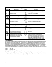
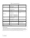
Table 2-2 lists the programming voltage and current values for each model. You can enter these values either from the front
panel or from a controller over the GPIB.
Table 2-2. Programming Voltage and Current Values
Agilent Model Full Scale Max. Prog. Full Scale Max. Prog. Max. Prog.
Voltage Voltage Current Current Overvoltage
Agilent 6680A
5V 5.125V 875A 895A 6.25V
Agilent 6681A 8V 8.190V 580A 592A 10.0V
Agilent 6682A 21V 21.50V 240A 246A 25.2V
Agilent 6683A 32V 32.75V 160A 164A 38.4V
Agilent 6684A
40V 41.00V 128A 131A 48.0V
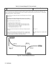
General Measurement Techniques
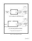
Figure 2-1 shows the setup for the Constant Voltage tests. Measure the dc output voltage directly at the sense (+S and -S)
terminals. Connect these terminals for remote sensing (to the +S and -S terminals). Connect these terminals for local
sensing. Be certain to use load leads of sufficient wire gauge to carry the output current (see Chapter 4 of the Power Supply
Operating Manual). To avoid noise pickup, use coaxial cable or shielded pairs for the test leads. If you use more than one
meter or a meter and an oscilloscope, connect separate leads for each instrument to avoid mutual-coupling effects.
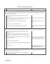
Performance Test Record Sheets
When performing the tests in this chapter, refer to the Performance Test Record sheets supplied at the end of this chapter.
Table 2-6 is for recording common information, such as, the test equipment used and the environmental conditions. Tables
2-7 through 2-11 are dedicated to specific models. Each sheet lists the acceptable test ranges for the model and provides a
place to record the results of the test.
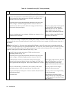
Note It is recommended that before you perform the tests in either Table 2-4 or Table 2-5, that you first locate
the appropriate Performance Test Record sheet from Tables 2-7 through Table 2-11 for your specific
model. Make a copy of this sheet, and record the actual observed values in it while performing the tests.
Use the sheets in Tables 2-7 through Table 2-11 as master reference sheets to run copies at any time.