


70 Troubleshooting
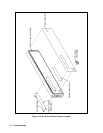
A4 AC Input Assembly
To remove the A4 AC Input Board first remove the GPIB board then disconnect these cables from the following connectors
at the GPIB board:
1. Disconnect the cables going to connector J417 and J420.
2. Disconnect the cable going to connector J419.
3. Remove the three (3) fuse assemblies inside rear of power supply to free the wires going to E400, E401, and E402 on
the AC Input Board.
4. Remove the holding screw at the center of board just to the left of the 3-phase choke.
5. Disconnect phone cable going to J108.
6. Slide the board to the right and lift out.
7. Other wires going to the board can now be removed/unsoldered.
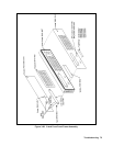
A5 DC RAIL Assembly
Disconnect these cables from the following connectors at the A5 DC RAIL board:
1. Disconnect the cables going to four connectors: J430, J431, J432, and J433.
2. Disconnect the cable going to connector J440.
3. Remove the four (4) holding screws TORX T-15 holding the A5 DC RAIL board in place.
4. Lift the board out and remove/desolder any other wires preventing the board from being removed.
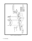
A6 BIAS Assembly
Disconnect the cables from the following connectors at the A6 BIAS Assembly board:
1. Disconnect cables from connectors J809, J821, J830, and J831 on the A6 BIAS Board.
2. Remove two (2) holding screws at top side of board.
3. Slide board upward until board is free of slotted standoffs. There is one of these standoffs at the top of the board and
two at the bottom. Wiggle the board slightly to clear all three standoffs then lift the board out.
4. Once the board is free from its restraining standoffs, you can proceed to remove/unsolder any other wires/cables as
necessary to remove the A6 BIAS Board entirely.
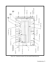
Note It is recommended that you label any connectors you disconnect from the A6 BIAS Board to facilitate the
reinstallation of these cables/wires back to their correct locations later. If you should have trouble later in
determining which cable goes to which connector during reinstallation, refer to the cabling diagram in
Chapter 6.
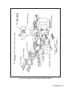
A3 FET Board
Follow this procedure to remove the A3 FET Board:
1. Remove the four (4) holding screws that secure the two black caps over the Rectifier HS assembly.
2. Once these caps are removed, you can remove the Rectifier HS which faces the A3 FET Board.
3. Disconnect two connectors, P430 and P431, at the A5 DC RAIL assembly.
4. Disconnect two connectors P/O cable assemblies P/N 5080-2283, at the A5 DC RAIL assembly.
5. You can now lift out the A3 FET board and remove/unsolder any other wires necessary to fully remove the A3 board.