


Diagrams 117
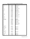
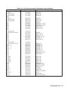
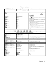
Table 6-3. Test Points
TEST POINT No. & Loc. Signal Tested Measurement and Conditions
A2 GPIB BOARD
J106-4
Primary/chassis ground Connect meter or scope common here. Then
make measurements at test points
through
.
U101- 1
+ 5V primary bias + 5V + 0.2V
U101-6
PCLR
Goes high for approximately 40 ms at power on,
then goes low.
U101-8
PCLR*
Held low for approximately 40 ms at power on,
then goes high.
U110-3
STX
Primary transmit to secondary serial data line.
Toggles between 0 and +5V.
U111-6
SRX
Primary receive from secondary serial data line.
Toggles between 0 and +5V.
U119-4
FPRX
Primary receive from front panel serial data
line. Toggles between 0 and +5V.
U119-18
FPTX
Primary transmit to front panel serial data line.
Toggles between 0 and +5V.
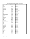
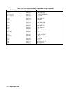
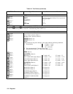
AC Input Board
Connect meter between TP and
,
or
and
,
or
and
,
and measure approximately 220VAC or
440VAC. Measurements at test points Rthrough X.
J418-1/J417-7
AC Mains Voltage
J418-2/J417-8
AC Mains Voltage
J418-3/J417-9
AC Mains Voltage
K402 coil
24VDC Coil Voltage Turns on PS, and after power-on initialization
test, reads approximately 24VDC.
DC Rail Board
J430-1 (+) to J430-2 (-)
Rail #1 Voltage Measure approximately 290VDC
J431-1 (+) to J431-2 (-)
Rail #2 Voltage Measure approximately 290VDC
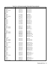
Bias Board
J801-4 to J801-5
GPIB 5V Bias
+15 ± 0.9V measure approx. 11VAC
J801-1 (+) to J801-2 (-)
Fan voltage Measure 24VDC
J827-1 (+) to J827-2 (-)
Inrush relay coil Measure 24VDC
J827-1 (+) to J827-3 (-)
Rail relay coil Measure 24VDC after power-on initialization
test.
R331
24V Primary Measure approximately 34VAC
R330
-15Vs secondary bias
-15 ± 0.9V
+C354
-25V -22.5V to -27.5V
U310-16
RELAY ON*
0V
U308-6
RESET 0V
U308-7
BIAS OK
+5V