


Principles Of Operation 81
4
Principles Of Operation
Introduction
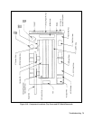
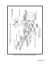
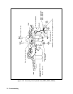
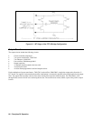
Figure 4-3 (at the end of this chapter) is a block diagram showing the major circuits within the power supply. The power
supply consists of the following circuits:
• A1 Front Panel Board ckts.
• A2 GPIB ckts.
• A10 Control Board including the secondary interface ckts, CV/CC control ckts, switching/downprogramming control
ckts.
• Power circuits on the A4 AC Input Board.
• A3 FET Assembly ckts.
• A5 DC Rail Board ckts.
• Output bus circuits which include the A7 Snubber Board, A8 Slow Sense Board, and A9 Downprogrammer Board
ckts.
• Output rectifiers and filter capacitors.
• Ferrite cores mounted on the output bus form the output filter inductors.
• A6 Bias Board supply which supplies low-voltage, low-power, bias voltages where required.
Each block in Figure 4-3 identifies a schematic diagram in Chapter 6 where the circuits are shown in detail. You can refer
to the component location diagrams in Chapter 6 to locate specific components mentioned in this description. Chapter 6
also has a cabling diagram showing the circuit board interconnections.
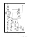
A2 GPIB Board
Circuits on the A2 GPIB board provide the interface between the GPIB controller and the power supply. All
communications between the power supply and the GPIB controller are processed by the GPIB interface and primary
microprocessor circuits on the A2 board.
The primary microprocessor circuits (microprocessor, U114, ROM U106, and RAM U108) decode and execute all
instructions and control all data transfers between the GPIB controller and the Secondary Interface on the A10 Control
Board. The primary microprocessor also processes measurement and status data received from the Secondary Interface.
A UART (universal asynchronous receive/transmit) IC (U112) on the A2 board converts data between the primary
microprocessor's 8-bit, parallel bus and the serial I/O port. The serial data is transferred between the primary interface and
the secondary interface via a programmed GAL (gated array logic) IC (U119) and optical isolator ICs (U110/U111).
These ICs isolate the primary interface circuits (referenced to earth ground) from the secondary interface circuits
(referenced to power supply common). The GAL IC also provides a serial I/O port to the A1 Front Panel Board to enable
front panel control of the power supply.
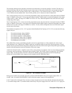
A serial link interface IC (U109) on the A2 GPIB Board allows up to sixteen supplies to be connected together and
programmed from one GPIB address. The first supply is the only supply connected directly to the GPIB controller and is
set to the primary GPIB address. The remaining supplies are set to secondary addresses and are linked (daisy chained)
together via the Jl/J2 phone jacks at the rear of each supply. The serial link configuration is described in the Power Supply
Operating Manual.