


Diagrams 115
6
Diagrams
Introduction
This chapter contains drawings and diagrams for troubleshooting and maintaining Agilent Series 668xA Power Supplies.
Unless otherwise specified, a drawing or diagram applies to all models of the series. Wiring connections to external
equipment are shown in the Power Supply Operating Manual.
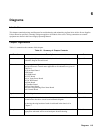
Chapter Organization
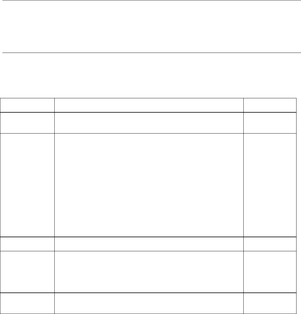
Table 6-1 summarizes the contents of this chapter.
Table 6-1. Summary of Chapter Contents
Function Description See
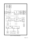
Interconnections Drawing identifying each circuit board, the cables between boards, and
schematic diagram for each board.
Figure 6-2
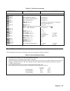
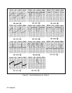
Schematics Show test points, signal mnemonics, component-location grid coordinates,
and specific notes. General notes applicable to all schematics are given in
Table 6-4.
Al Front Panel Board.
LED Board.
A2 GPIB Board.
A3 FET Board.
A4 AC Input Power Board.
A5 DC Rail Board.
A6 Bias Board.
A7 Snubber Board.
A8 Fast Sense Board.
A9 Down Programming/Slow Sense Board.
A10 Control Board.
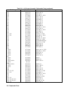
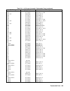
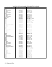
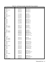
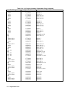
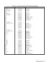
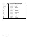
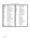
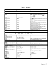
Signal names Table of signal name mnemonics Table 6-2
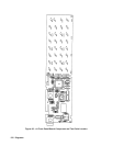
Parts location A drawing that shows the location of components on a circuit board is
located next to the above circuit board schematic diagram.
A drawing showing location of each circuit board in the chassis is in
Chapter 3.
Figure 3-18
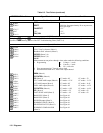
Test points Description of each test point. Location of each test point is shown on the
appropriate schematic and its associated parts location drawing.
Table 6-3