


Troubleshooting 57
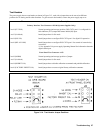
Test Headers
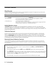
The power supply has two test headers as shown in Figure 3-15, each with a jumper that can be moved to different
positions for SA testing and for other functions. To gain access to the headers, remove the power supply top cover.
Pins Description
Primary Interface Test Connector A2J106 (Systems Supplies Only)
7 and 8 (FLT/INH) Normal operating (and storage) position. DIG CNTL port** is configured for
fault indicator (FLT) output and remote inhibit (RI) input .
1 and 2 (SA Mode) Install jumper here for SA mode.
3 and 4 (DIG I/O) Install jumper here to configure DIG CNTL port** for digital I/O operation .
5 and 6 (RELAY LINK) Install jumper here to configure DIG CNTL port** for control of external relay
accessories.
** See Appendix D in power supply Operating Manual for information about the
digital control port.
Front Panel Test Connector A1J3
7 and 8 (NORM) Normal operating (and storage) position of jumper.
1 and 2 (SA Mode) Install jumper here for SA mode.
3 and 4 (INHIBIT CAL) Install jumper here to disable calibration commands and prohibit calibration.
5 and 6 (FACTORY PRESET CAL) Install jumper here to restore original factory calibration constants.
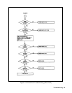
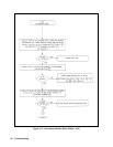
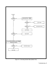
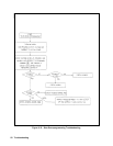
Figure 3-14. Test Header Jumper Positions