


68 Troubleshooting
2010 IF Err THEN
2020 PRINT "An error occurred during the EEPROM read/write, Check for"
2030 PRINT "programming errors. Initialization data may be incorrect."
2040 STOP
2050 END IF
2060 !
2070 PRINT "Operation complete. Program stopped."
2080 STOP
2090 !
2100 Ps_error: ! Error handling subroutine
2110 OUTPUT @Ps;"SYST:ERR?" ! Check for errors
2120 ENTER @Ps;Err
2130 RETURN
2140 !
2150 END
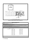
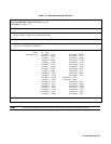
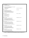
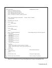
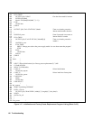
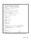
Figure 3-17. Initialization and Factory Preset Replacement Program Listing (Sheet 5 of 5)
Disassembly Procedures
Shock Hazard: To avoid the possibility of personal injury, remove the power supply from service before
removing the top cover. Turn off the ac power and disconnect the line cord, GPIB cable, load leads, and
remote sense leads before attempting any disassembly. Any disassembly work must only be performed by
a qualified support technician.
Observe that the DC RAIL assembly LEDs (DS420 & DS421) are fully extinguished (no live voltages
present) before attempting any disassembly work. Any disassembly work must only be performed by a
qualified support technician.
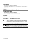
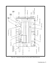
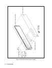
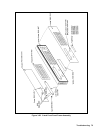
Cable connections are shown in Figure 6-2 of Chapter 6 and component part numbers are given in Chapter 5. Reassembly
procedures are essentially the reverse of the corresponding disassembly procedures.
Tools Required
þ TORX screwdriver size T-15 (for most all retaining screws).
þ TORX screwdriver size T-20 (for power supply carry straps).
þ Seven (7) mm metric hex driver (to remove GPIB read connector).
þ Pencil, paper, and labels to make notes to aid in the reinstallation of components.
þ Work at a static-free station such as a table covered with static-dissipative laminate or with a conductive table mat
(Agilent P/N 9300-0797, or equivalent) using a conductive wrist strap where necessary, such as, Agilent P/N
9300-0969 or 9300-0970.