


Verification 17
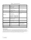
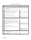
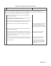
Table 2-4. Constant Voltage (CV) Tests (continued)
Action
Normal Result
CV Source Effect (cont)
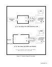
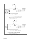
2 Set the transformer to the nominal ac line voltage. Connect the DVM
across +S and -S (see Fig. 2-1).
3 Turn on the power supply and program the current to its maximum
programmable value and the voltage to its full-scale value (see Table 2-2).
4 Adjust the load to produce full-scale current (see Table 2-2) as shown on
the front panel display.
CV annunciator is on. If it is not, adjust
the load to slightly reduce the output
current until the annunciator comes on.
5 Adjust the transformer to decrease the ac input voltage to the low- line
condition (174Vac or 191Vac). Record the output voltage reading of the
DVM.
6 Adjust the transformer to increase the ac input voltage to the high-line
condition (220Vac or 250Vac). Record the output voltage reading on the
DVM.
7 Check test result.
The difference between the DVM
readings in steps 5 and 6 are within the
specified Source Effect limits.
CV Noise (PARD)
Periodic and random deviations (PARD) in the output (ripple and noise) combine to produce a residual ac voltage
superimposed on the dc output voltage. This test measures CV PARD, specified as the rms and peak-to-peak output
voltages over the frequency range of 20Hz to 20MHz.
1 Turn off the power supply and connect an a-c coupled oscilloscope across
the + and -output terminals (see Fig. 2-1). Set the oscilloscope bandwidth
limit to 20MHz (30MHz for the Agilent 54504A) and use an RF tip on the
oscilloscope probe.
2 Turn on the power supply and program the current to its maximum
programmable value and the voltage to its full-scale value (see Table 2-2).
3 Adjust the load to produce full-scale current (see Table 2-2) as shown on
the front panel display.
CV annunciator is on. If it is not, adjust
the load to slightly reduce the output
current until the annunciator comes on.
4 Record the amplitude of the waveform.
Amplitude is within the specified PARD
Peak-to-Peak limits.
5 Replace the oscilloscope connection with an ac rms voltmeter.
6 Record the reading obtained in Step 5.
Amplitude is within the specified PARD
rms limits.