


Introduction
1–6 975-0083-01-01
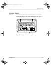
System components
System
description
The Xanbus system includes the System Control Panel and other Xanbus-
enabled devices. Each device interacts and communicates with the other
devices.
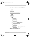
Network
diagram
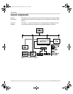
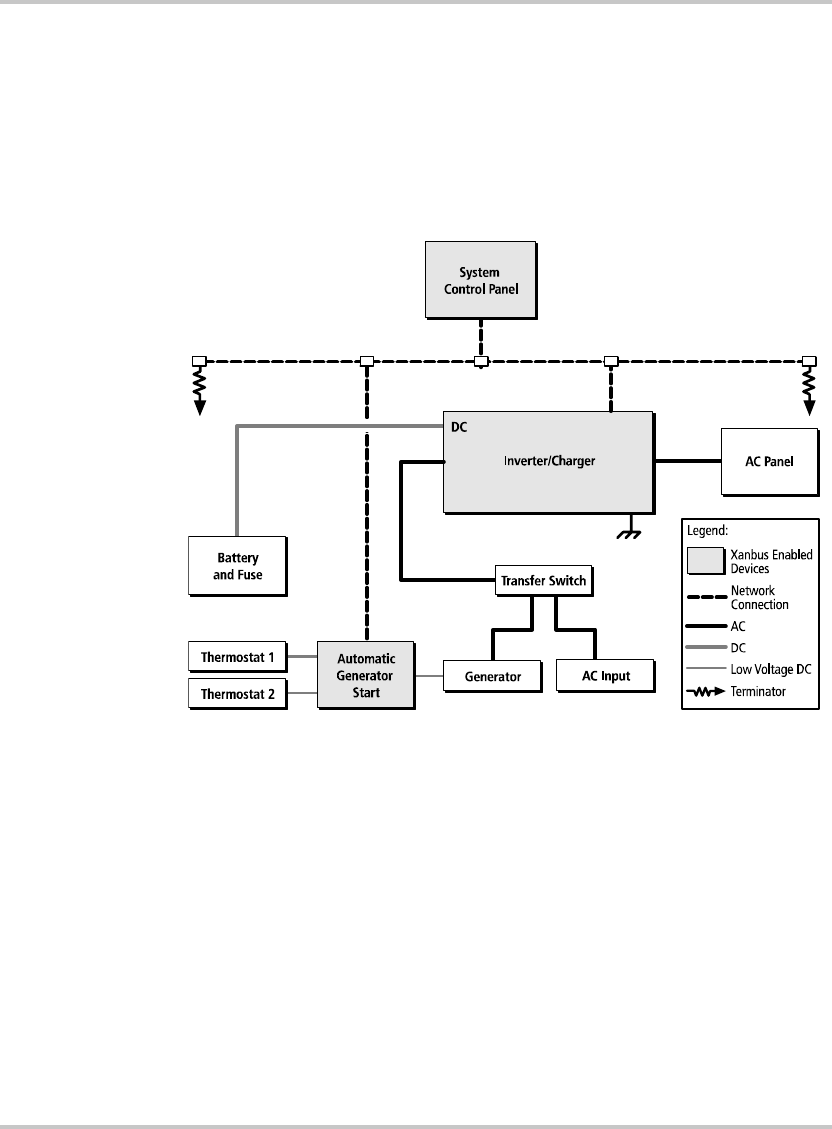
In Figure 1-3, network connections are represented by dotted lines and
conventional electrical connections are represented by solid lines.
Figure 1-3
Network diagram
AC In
AC Out
scp_manual.book Page 6 Wednesday, March 10, 2010 5:03 PM