


2.2 REMOVING/REPLACING THE OUTPUT 2/OUTPUT 3 OPTION
PCBs
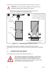
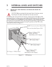
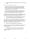
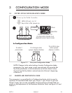
With the instrument removed from its housing:
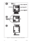
1. Gently push the rear ends of the CPU PCB and Power Supply PCB apart
slightly, until the two tongues on each of the Output 2/Output 3 Option
PCBs become disengaged - see Figure 2-2B; The Output 2 Option PCB
tongues engage in holes in the Power Supply PCB and the Output 3 Option
PCB tongues engage in holes on the CPU PCB.
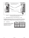
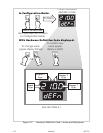
2. Carefully pull the required Option PCB (Output 2 or Output 3) from its
connector (Output 2 Option PCB is connected to the CPU PCB and Output
3 Option PCB is connected to the Power Supply PCB) - see Figure 2-2C.
Note the orientation of the PCB in preparation for its replacement.
Adjustments may now be made to the link jumpers on the CPU PCB, the Output
2/Output 3 Option PCBs (if DC output) and (if fitted) the DC Output 1 PCB. The
replacement procedure is a simple reversal of the removal procedure.
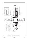
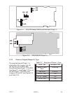
2.3 REMOVING/REPLACING THE RS485 COMMUNICATIONS
OPTION PCB OR REMOTE RUN/HOLD OPTION PCB
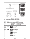
The RS485 Communications Option PCB or Remote Run/Hold Option PCB is
mounted on the inner surface of the Power Supply PCB and can be removed when
the instrument is removed from its housing (see Subsection 2.1) Figure 2-3
illustrates the removal/replacement procedure. It is not necessary to remove the
Output 2/Output 3 Option PCBs to perform this procedure.
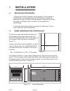
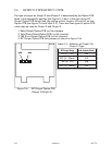
2.4 REPLACING THE INSTRUMENT IN ITS HOUSING
To replace the instrument, simply align the CPU PCB and Power Supply PCB with
their guides and connectors in the housing and slowly but firmly push the
instrument into position.
CAUTION: Ensure that the instrument is correctly orientated. A stop
will operate if an attempt is made to insert the instrument in the
wrong orientation (e.g. upside-down). This stop must not be
overridden.
S077-2 Volume I 2-3