


2-4 Volume II O077-2
Parameter Function Adjustment Range
Default
value
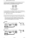
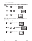
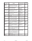
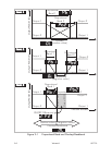
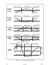
ON/OFF
Differential
Switching differential for one output or
both outputs set to ON/OFF control
(PB1, PB2 or both = 0) - see Figure
2-1.
0.1% to 10.0% of
input span
0.5%
Setpoint Lock Enables/disables setpoint (SP)
adjustment in Base Mode.
OFF - SP adjustable
ON - SP not
adjustable
OFF
Recorder Output
Scale Maximum
Process variable or setpoint value (as
applicable) for which the recorder
output is a maximum
-1999 to 9999
(decimal point
position as for input
range)
Input
Range
Maximum
Recorder Output
Scale Minimum
Process variable or setpoint value (as
applicable) for which the recorder
output is a minimum
-1999 to 9999
(decimal point
position as for input
range)
Input
Range
Minimum
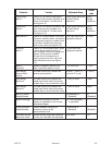
Output 1 Power
Limit
Limits Output 1 power level (to protect
the process)
0% to 100% of full
power
100%
Output 1 Cycle
Time
Limits the frequency of operation of
output relay to maximise relay life
0.5, 1, 2, 4, 8, 16, 32,
64, 128, 256 or 512
secs.
32 secs.
Output 2 Cycle
Time
Limits the frequency of operation of
output relay to maximise relay life
0.5, 1, 2, 4, 8, 16, 32,
64, 128, 256 or 512
secs.
32 secs.
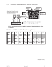
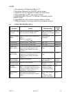
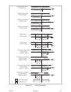
Process High
Alarm 1
If Alarm 1 is a Process High Alarm, the
value of the process variable at or
above which Alarm 1 will be active (see
Figure 2-2)
Input Range Minimum
to Input Range
Maximum
Input
Range
Maximum
Process Low
Alarm 1
If Alarm 1 is a Process Low Alarm, the
value of the process variable at or
below which Alarm 1 will be active (see
Figure 2-2)
Input Range Minimum
to Input Range
Maximum
Input
Range
Minimum
Band Alarm 1 If Alarm 1 is a Band Alarm, the band of
process variable values, centred on the
(program) setpoint, outside which the
process variable will cause this alarm to
be active (see Figure 2-2)
0 to input span from
(program) setpoint
5 units
Deviation
Alarm 1
If Alarm 1 is a Deviation Alarm, gives a
value above (positive value) or below
(negative value) the (program) setpoint.
If the process variable deviates from
the setpoint by a margin greater than
this value, the alarm becomes active
(see Figure 2-2)
±input span from
(program) setpoint
5 units
Alarm 1
Hysteresis
Defines a hysteresis band on the “safe”
side of the Alarm 1 value
1 to 250 units 1 unit