


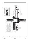
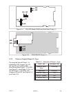
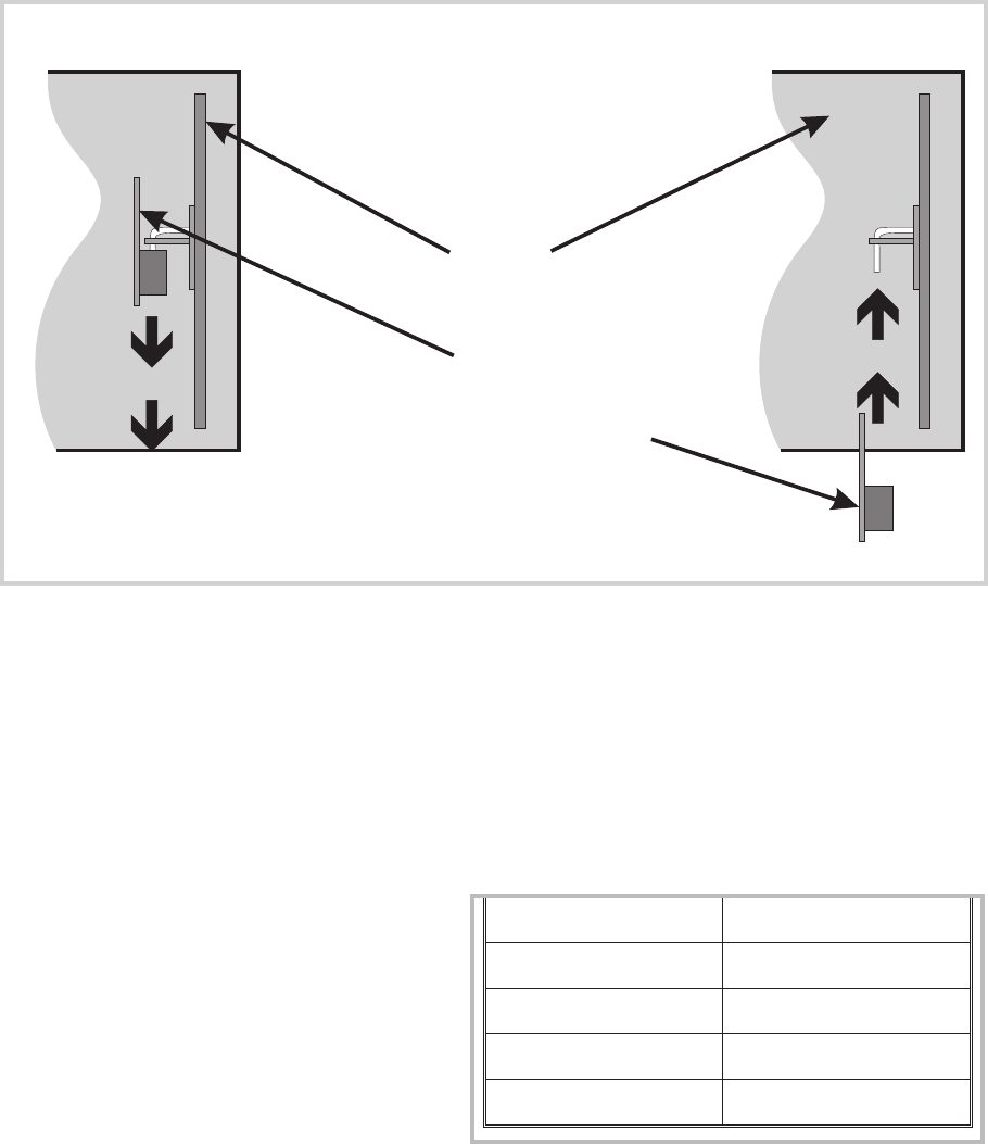
2.5 SELECTION OF INPUT TYPE AND OUTPUT 1 TYPE
The selection of input type and Output 1 type is accomplished on link jumpers on
the CPU PCB. The CPU PCB may be either of two forms: (a) for a relay, solid state
or SSR drive Output 1 (see Figure 2-4) or for a DC Output 1 (see Figure 2-5).
2.5.1 Input Type
The required input type is selected on
link jumpers LJ1/LJ2/LJ3 on the CPU
PCB (see Figure 2-4 or 2-5, as
appropriate, and Table 2-1).
2-4 Volume I S077-2
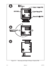
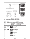
PSU PCB
RS485 SerialComms. Option PCB
or
Remote Run/Hold Option PCB
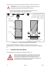
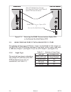
REMOVAL REPLACEMENT
View of Controller from the rear.
For clarity, the Output 2 and Output 3
Option PCBs are not shown.
Figure 2-3 Removing the RS485 Communications Option PCB
or the Remote Run/Hold Option PCB
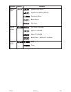
Input Type Link Jumpers Fitted
RTD or DC (mV) None (Parked)
Thermocouple LJ3
DC (mA) LJ2
DC (V) LJ1
Table 2-1 Selection of Input Type