


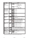
NOTES:
1. If Output 2 is a relay/SSR drive/solid state output, it may be a control
output (COOL), an event output or an alarm output; if it is set to be a DC
output, it can only be a control output (COOL).
2. If Output 3 is a relay/SSR drive output (it cannot be a solid state output),
it can only be an event output or an alarm output; if it is set to be a DC
output, it can only be a recorder (i.e. retransmitted process variable or
setpoint) output.
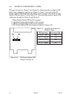
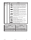
The maximum setting available for this code is 4887. For example, the code for a
thermocouple input, DC 4 - 20mA primary output (Output 1) and relay Output 3
would be 2701.
NOTE: It is essential that this code is changed promptly
whenever there is a change to the instrument’s hardware
configuration (change of input/output type, alarm/recorder
output added/removed etc.). The instrument software depends
upon this code to ensure that the instrument operates
correctly.
This code may be viewed as a Read Only display in Base Mode (see Volume II,
Subsection 1.11).
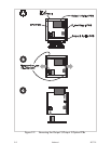
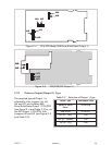
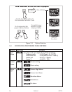
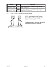
3.3 OPTION SELECTION
This indicates the option fitted (Communications Option, Remote Run/Hold option
or no option at all). It is accessed whilst the Hardware Definition Code is
displayed (see Figure 3-3).
S077-3 Volume I 3-3
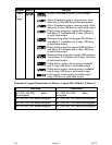
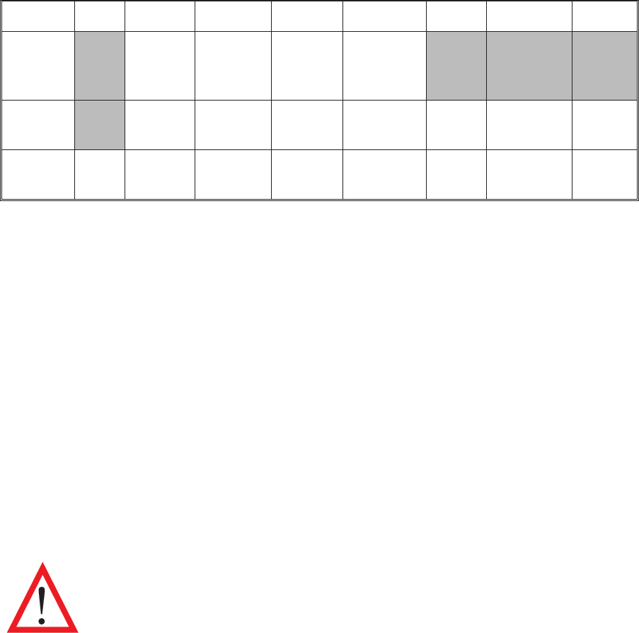
Value 0 1 2 3 4 5 7 8
Input RTD/
Linear
DC mV
Thermo-
couple
Linear
DC mA
Linear
DC V
Output
1
Relay SSR
Drive
DC
0 - 10V
DC
0 - 20mA
DC
0-5V
DC
4 - 20mA
Solid
State
Output
2/3
Not
fitted
Relay SSR
Drive
DC
0 - 10V
DC
0 - 20mA
DC
0-5V
DC
4 - 20mA
Solid
State*
* Output 2 only
Table 3-1 Hardware Definition Code - Input/Output Type Selection