


264
Appendix C: Best Practices for Low Power Control Signal Wiring
Low power analog signals are commonly used for proportional
control signal wiring in HVAC applications. Following are a
series of best practices for the prevention of corruption of these
signals due to electro-magnetic interference (“EMI”).
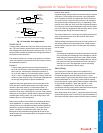
EMI is typically caused by coupling of the electro-magnetic field
that surrounds all wires carrying current. It may also be caused
by radio frequency sources such as “walkie talkies” using
amplitude modulated signals. A strong EM field can induce
electrical noise in wires up to 2 V in amplitude. The strongest
coupling comes between closely spaced, parallel wires.
Inductive and high power motor loads are some of the strongest
sources of EMI, along with electronics lighting ballasts,
dimmers, and variable frequency motor drives. More potential
EMI sources in a building mean that greater attention needs to
be paid to effective wiring practices.
All control wiring should consist of twisted pairs of wires, which
resist interference better than straight, non-twisted conductors.
Stranded conductors offer less resistance to current flow than
solid wires, and are more flexible making them easier to install;
however, care must be taken to ensure that all the conductors in
the wire are properly installed and that “whiskers” do not short
out any wiring connections.
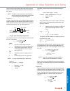
Shielded Wiring
Control signals can be protected from EMI using shielded wire. The
more continuous the shield, the more effective it is. Braided shield is
commonly used for microphone cables because of its superior
flexibility. HVAC wiring is fixed, does not require high flexibility during
use, and is better served with lower cost cables using continuous foil
shielding and a “drain wire”.
1. All signal wiring in hospitals should be shielded to prevent the
potential for interference with medical equipment such as high
power MRI and CT scanners.
2. All 0~10 Vdc control signals should be run in shielded cable.
EMI noise can be interpreted as control signaling, depending
on the noise suppression circuitry in the controlled equipment.
3. Long runs of wiring from 24 V power supply transformers
should be shielded in heavy electrical noise environments to
prevent EMI from coupling through the actuator’s power sup-
ply.
4. In typical commercial buildings, 2~10 Vdc signals do not
require shielded wiring.
5. Current flow is much more difficult to induce in wiring than
voltage, and current-based control signals usually do not
require shielded cable except in heavy industrial applica-
tions.
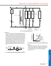
a. If the terminal equipment only accepts voltage input,
install a 500 ohm, ¼ Watt (or larger), 1% resistor across
the control input terminals to convert a 4~20 mA(dc) sig-
nal to 2~10 Vdc.
b. If multiple actuators are connected in parallel, install this
resistor at the first actuator in the group.
c. Any standard resistor (“EIA”) value between 490 and 510
ohms is acceptable, and can be purchased at retail out-
lets that sell electronic components.
6. Floating, pulse-width modulated, and two-position actuators
use switched 24 Vac control or power signals and so rarely
require shielded wiring.
Wiring Techniques
1. No wiring should ever be assumed to be interference-proof.
Never strap signal cables to other conductors or conduit,
especially line voltage.
2. Never run signal wires in raceways or wiring troughs with
other conductors. Keep signal wires at least a yard away from
line voltage wiring. Higher voltage wiring requires greater
separation.
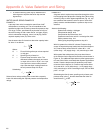
3. When necessary, cross line voltage conductors with signal
wiring at 90° (right angles), to minimize signal coupling.
4. Electromagnetic shielding is a static phenomenon; any cur-
rent running through the shield will negate any protection the
shield may have provided. Only ground (or “earth”) a shield
drain wire at one point, preferably where the signal will be the
weakest, for example: at the actuator.
a. Do not ground the secondary of the 24 V power supply in
the control system. This will create a secondary current
path and negate the protection of any shielding.
b. If there is a burner ignition system, power it with its own
transformer and use an interface relay for isolation, if nec-
essary.
c. Use relays with built-in coil arc suppression, such as a
Honeywell R8229.
5. Insulate all exposed shielding and drain wire joins and splices
so that they cannot contact electrical ground, especially junc-
tion boxes and conduit. Do not use the ground screw of a
junction box as a tie point. Use a separate electrical ground
wire if required for safety extra-low voltage wiring by local
code.
6. Both rigid and flexible conduit are continuously grounded
(“bonded”) for electrical safety, and cannot function as a signal
shield. Where local codes require mechanical protection for
all wiring, shielded signal cable may be run inside conduit, fol-
lowing the practices listed above.
Additional References
Most of these wiring techniques were developed to protect the
very low-strength signals in audio recording. The 20 mA current
loop signal was originally used with teletype (“TWX”) equipment
communicating over telephone lines and adapted for
proportional analog control signaling in industrial process
control. Further information and background theory can be
found in:
1. Audio Engineering Handbook, edited by Blair K. Benson,
McGraw-Hill
2. Handbook for Sound Engineers, by Glen Ballou
3. Standard Handbook of Audio Engineering, by Jerry Whi-
taker and Blair K. Benson, McGraw-Hill.
Appendix C: Best Practices for Low Power Control Signal Wiring