


133
SUBMITTAL SHEETS
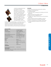
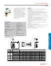
VBN3
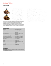
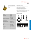
The VBN3 Three-Way Control Ball
Valves control hot and chilled water
with glycol solutions up to 50% in
heating, ventilating, and air
conditioning (HVAC) systems to
provide two-position or modulating
functions. These valve assemblies
can be ordered with or without
factory-mounted non-spring return
or spring return direct-coupled
actuators (DCA).
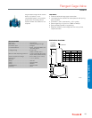
SPECIFICATIONS
Valve Type ............................................Control Ball Valve
Body Pattern ........................................Three-way
Flow Characteristic ...............................Equal percentage with
patented control insert.
Connection Type ..................................NPT Female
Controlled Medium ...............................Hot/Chilled Water with up to
50% Glycol
Leakage Rating ....................................ANSI Class IV
Maximum Safe Operating Pressure .....360 psi (2482 kPa)
Fluid Temperature Range .....................-22 F to 250 F (-30 C to 121 C)
Materials
(Body) ...................................................Brass
(Stem) ...................................................Brass
(Seat) ....................................................Teflon® seals with EPDM
O-rings
(Plug/Ball/Disc) .....................................Nickel-plated brass ball
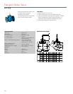
FEATURES
• Sizes from 1/2 to 2-1/2 in. with internal (female) NPT
connections.
• Equal percentage or linear flow characteristics.
• Choice of four, factory-installed actuation control schemes:
Floating, Modulating (2-10 V), Spring Return 2-Position,
Spring Return Modulating/Floating.
• Field configurable for normally open or normally closed fail-
safe position.
• Removable manual operating handle to control valve during
installation or in an event of power failure.
• ANSI Class IV seat leakage specification (0.01% of C
v
).
• Optional NEMA 3R (IP54) rated enclosure for outdoor
applications.
• Actuator can be mounted on the valve in any of four
positions.
• Wide C
v
choices from 0.33 to 109.
• Valve installs in a globe valve "T" pattern, no extra elbows or
piping required.
• Nickel-chrome plated brass valve ball and stem.
• Mixing or Diverting control.
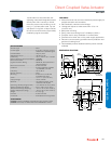
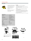
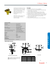
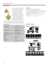
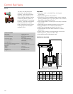
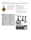
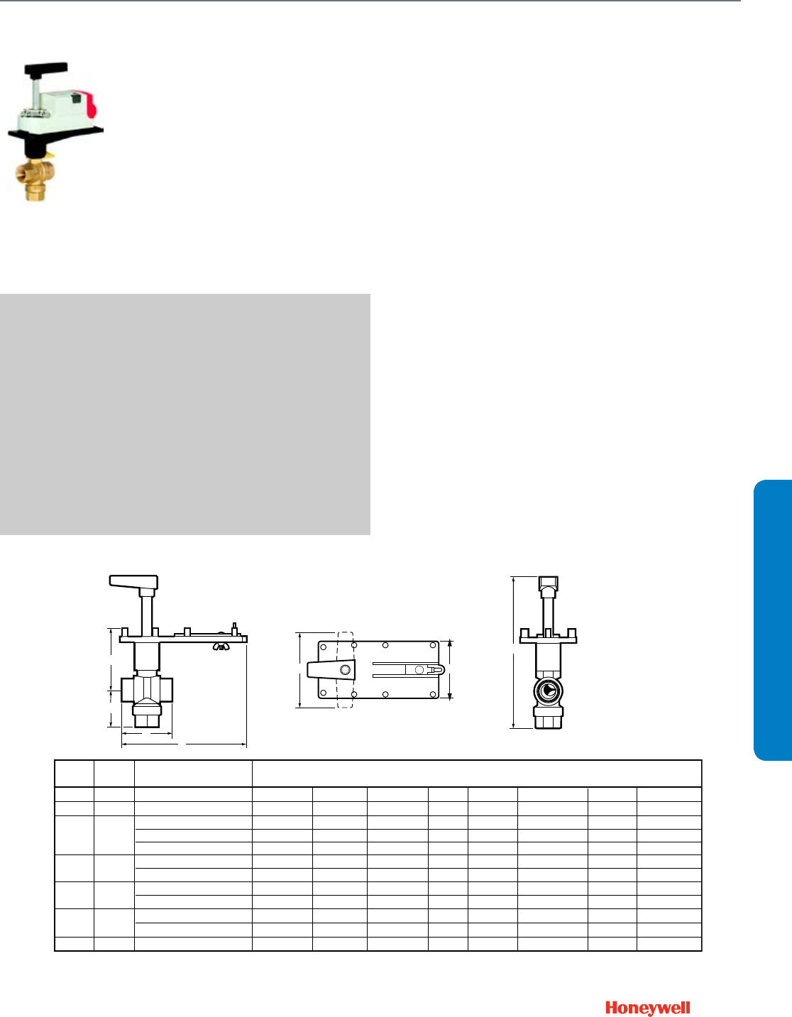
DIMENSIONS DIAGRAM
M13730
ED
B
G
A
C
F
Pipe Model C
V
Dimensions inches (mm) Weight
Size No. A B C D E F G lb (kg)
1/2" VBN3A 0.33, 0.59, 1.0, 2.4, 4.3, 8.0 3-1/2 (90) 3-5/16 (84) 7 (178) 3 (76) 4 (102) 9-3/8 (238) 2-3/8 (60) 2.4 (1.1)
3/4" VBN3B 0.40, 0.66, 1.3, 2.4, 3.8, 11.0 2-13/16 (71) 3-5/16 (84) 6-1/2 (168) 3 (76) 4 (102) 8-13/16 (224) 2 (51) 2 (0.9)
1" VBN3C 0.40, 0.65, 1.3, 2.3, 3.5 3-13/16 (97) 3-5/16 (84) 7-5/16 (186) 3 (76) 4 (102) 9-1/2 (241) 2-3/4 (70) 2.8 (1.3)
8.6, 22 3 (76) 3-13/16 6-13/16 (173) 3 (76) 4 (102) 9-13/16 (249) 2-5/8 (67) 2.6 (1.2)
4.5, 14.9, 31 4-1/2 (114) 4 (102) 7-13/16 (198) 3 (76) 4 (102) 10-13/16 (275) 3-1/4 (83) 3.3 (1.5)
1-1/4" VBN3D 4.1, 8.7, 19.0 3 (76) 3-13/16 6-13/16 (173) 3 (76) 4 (102) 9-13/16 (249) 2-1/2 (64) 2.5 (1.1)
12.7, 27, 34 3-5/8 (92) 4 (102) 7-5/16 (186) 3 (76) 4 (102) 10-5/16 (262) 2-3/4 (70) 2.8 (1.3)
1-1/2" VBN3E 4.0, 8.3, 13.4, 32 4-1/2 (114) 4 (102) 7-13/16 (198) 3 (76) 4 (102) 10-13/16 (275) 3-1/4 (83) 3.3 (1.5)
24, 61 4 (102) 4-1/2 (114) 7-5/16 (186) 3 (76) 4 (102) 11 (279) 3-1/4 (83) 3.3 (1.5)
2" VBN3F 24, 38, 57 4 (102) 4-1/2 (114) 7-5/16 (186) 3 (76) 4 (102) 11 (279) 3-1/4 (83) 3.3 (1.5)
83, 109 5 (127) 5-13/16 7-13/16 (198) 3 (76) 4 (102) 12-5/16 (313) 3-3/4 (95) 3.8 (1.7)
2-1/2" VBN3G 38, 74, 100 5 (127) 5-13/16 7-13/16 (198) 3 (76) 4 (102) 12-5/16 (313) 3-3/4 (95) 3.8 (1.7)
Control Ball Valve
VBN3